INSTRUCTIONS FOR ADJUSTERS AND MACHINISTS
Needle Vibrating Mechanism
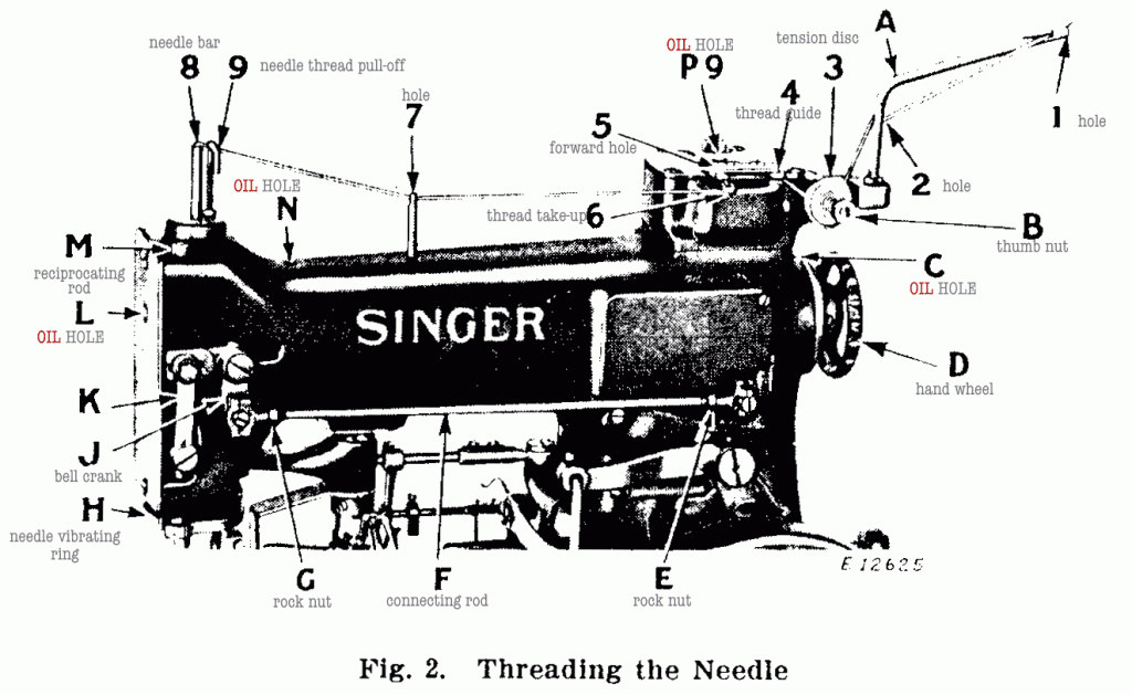
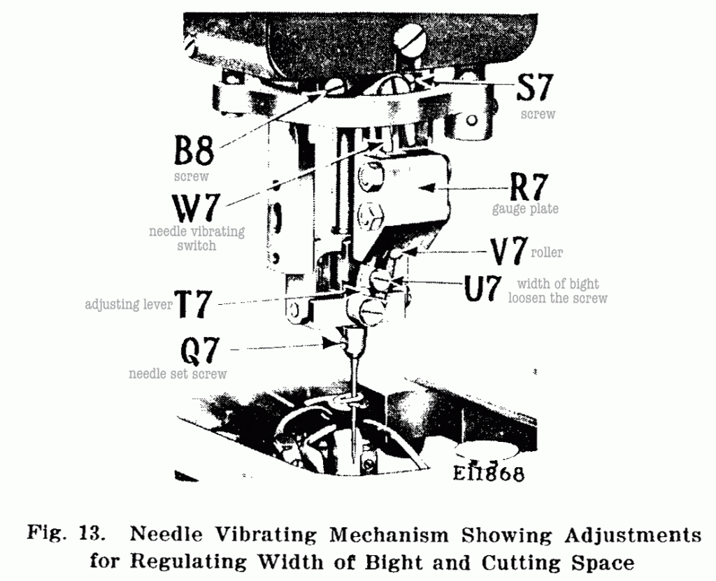
¶ The needle vibrating mechanism is actuated by means of a cam on the upright shaft. When this shaft starts to rotate, the cam moves the connecting rod (F, Fig. 2) back and forth, causing it to rock the bell crank (J, Fig. 2) which in turn moves the link (K, Fig. 2) up and down, carrying with it the reciprocating rod (M, Fig. 2) which has the vibrating ring (H, Figs. 2 and 12) attached to its lower end. ¶ As the vibrating ring moves up and down, it swings the needle vibrating switch (W7, Fig. 13) side- ways, causing the roller (V7, Fig. 13) to be switched from one groove to the other in the gauge plate (R7, Fig. 13). The roller (V7) is mounted upon the needle bight adjusting lever (T7, Fig. 13) which in turn is mounted on the bridge of the needle bar so that when the roller is switched in the grooves of the gauge plate (R7), the needle is vibrated from side to side.
To Align the Needle
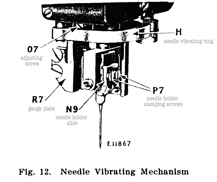
¶ To ascertain the alignment of the needle, loosen the needle holder clamping screws (P7, Fig. 12) and slide the needle holder so that the left hand edge is flush with the corresponding edge of the needle holder slide, as shown at N9 in Fig. 12, and tighten the screws. ¶ Now clamp a piece of light card under the clamp checks, raise the work clamp carrier side throw lever lock pin (B6, Fig. 9) up and out of the pattern wheel (U5, Fig. 9) and then with wrench on pattern wheel clamping nut (S5, Fig. 9), turn the machine up the first side of buttonhole, at the same time making a row of light punctures in the card with the needle on the slit or central vibration. ¶ Continue up and around the eye. ¶ The needle point, while coming down the last side of the button- hole, should exactly enter the card in the first line of punctures. If the two lines do not coincide, it will be necessary to adjust the gauge plate (R7, Fig. 13) to the right or left as may be required. ¶ While the machine is still on the last side of the buttonhole with the gauge plate (R7) towards you, move the needle vibrat- ing ring (H, Fig. 12) to its lowest point, then loosen the two screws (S7 and B8, Fig. 13) and turn the adjusting screw (07, Fig. 12) to bring the two lines of needle punctures in line with each other, then tighten the two screws (S7 and B8). ¶ Turn the machine by hand and note the movement of the roller (V7, Fig. 13) as it passes from the slot of the gauge plate (R7) into the needle vibrating switch (W7, Fig. 13) and then from the switch (W7) back into the second slot of the gauge plate (R7). ¶ Should the roller drag upon the side wall of the gauge plate or switch, it will be necessary to change the length of the rod (F, Fig. 2). ¶ After making adjustments of the rod (F), the lock nuts (E and G, Fig. 2) should be tightened. ¶ After making the above adjustments, turn the machine with the wrench on the pattern wheel clamping nut (S5, Fig. 9) to the starting position as referred to under “Caution” on page 60.
To Regulate the Cutting Space
¶ Having followed the instruction for aligning the needle, again clamp a piece of light card under the clamp checks, raise the work clamp carrier side throw lever lock pin(B6, Fig. 9) up and out of the pattern wheel (U5, Fig. 9) and then with wrench on pattern wheel clamping nut (S5, Fig. 9), turn the machine up the first side of the buttonhole, at the same time making a row of light punctures in the card with the needle on the slit or central vibration. ¶ While on the first side of the buttonhole, loosen the needle holder clamping screws (P7, Fig. 12) and slightly adjust the needle holder to the left. ¶ The needle, while coming down the last side of the buttonhole, should enter the card about .006 inch to the right of the first line of punctures. ¶ This distance may have to be changed according to the thickness and textures of the material being sewn, as the heavier grades of materials require more cutting space than the lighter fabrics and, therefore, a greater distance between the two parallel lines of needle punctures may be required.
To Regulate the Width of Bight.
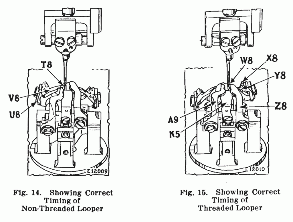
¶ The width of bight or stitch is regulated by the screw (U7, Fig. 13). To increase the width of bight or stitch, loosen the screw (U7) and move it upwardly. To decrease the width of bight, loosen the screw (U7) and move it downwardly. ¶ When changing the width of bight or lateral throw of the needle, it will be necessary to adjust the loop retainer (A9, Fig. 15) and the non-threaded looper (V8, Fig. 14), as instructed on pages TO REPLACE AND TIME NON-THREADED LOOPER and LOOP RETAINERS.
