To Remove the Work Clamp Plates
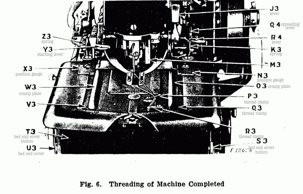
¶ When it is desired to remove the work clamp plates (O3 and W3, Fig. 6) from the machine, for the purpose of making adjustments, this can be done as follows: ¶ Unhook the two springs (K3 and Z3, Fig. 6) on the work clamp plates, then swing each plate outward at right angle to the machine and lift the plates from the machine.
To Regulate the Tensions
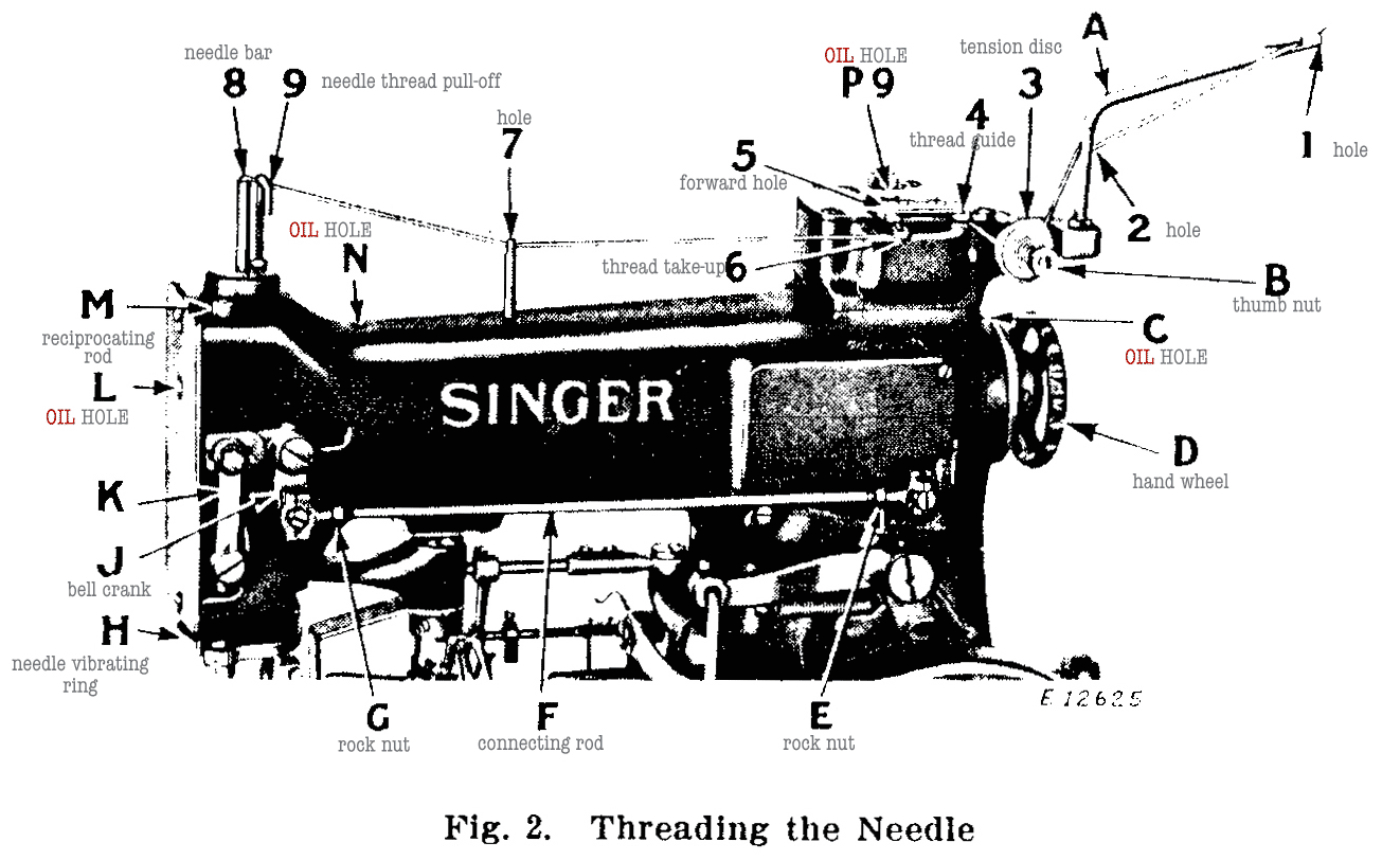
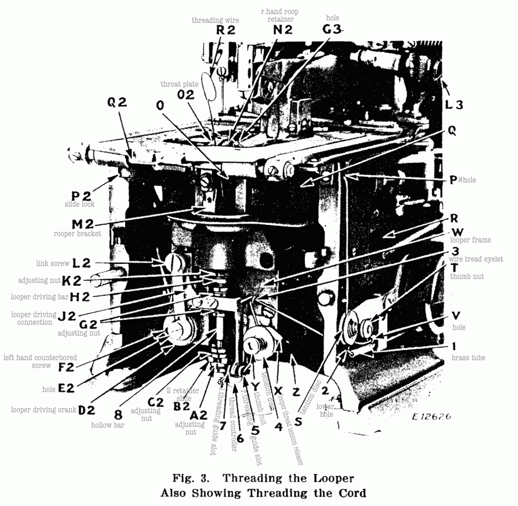
¶ The tension on the needle thread is regulated by the thumb nut (B, Fig. 2) at the right of the tension discs at the top of the machine. ¶ To increase the tension, turn this thumb nut over from you. To decrease the tension, turn this thumb nut over toward you. ¶ The tension on the needle thread should be sufficiently heavy to set the purl of the buttonhole on the underside of the work. ¶ The tension on the looper thread is regulated by the thumb nut (Y, Fig. 3) at the front of the tension discs inside the front of the bed of the machine. ¶ To increase the tension, turn this thumb nut over to the right. ¶ To decrease the tension, turn this thumb nut over to the left. ¶ The tension on the looper thread should be sufficient to balance the tension of the needle thread and give the desired character to the formation of the stitch. ¶ The tension on the cord is regulated by the thumb nut (T, Fig. 3). ¶ To increase the tension, turn this thumb nut over from you. ¶ To decrease the tension, turn this thumb nut over toward you. ¶ The tension on the cord should be light.
To Change the Style and Length of Buttonhole
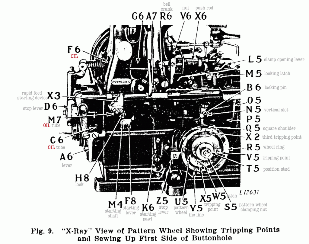
¶ When it is desired to make a different style and length of buttonhole it will be necessary to change the pattern wheel (U5, Fig. 9), buttonhole cutting block (T2, Fig. 5) and the cutting knife (D3, Fig. 5). ¶ Some pattern wheels produce two styles of buttonholes as shown in the lists on pages 5 to 10 in- clusive, in which cases the following adjustment is necessary to change from one style of buttonhole to the other.
¶ To Adjust Machines 99w130 and 99w131 for making Eyelet- end Buttonholes (with large size eye) without a Bar. ¶ Having placed the desired pattern wheel in the machine, see that the locking pin (B6, Fig. 9) rests on the straight ledge of the work clamp side throw lever as shown in Fig. 9, then place the correct buttonhole cutting block and knife in the machine. (See list of cutting blocks and knives given on pages 5 to 8 inclusive.)
¶ To Adjust Machines 99w130 and 99w131 for making Eyelet- end Buttonholes (with medium size eye) with a Taper Bar or without a Bar, also Straight Buttonholes. ¶ Having placed the desired pattern wheel in the machine, see that the locking pin (B6, Fig. 9) rests in the vertical slot (N5, Fig. 9) of the work clamp side throw lever, then place the correct buttonhole cutting block and knife in the machine. (See list of cutting blocks and knives given on pages 5 to 8 inclusive.)
¶ To Remove the Pattern Wheel, draw the lever (A6, Fig. 9) toward you so as to swing the stop lever operating plate (Z5, Fig. 9) back out of range of the pattern wheel. ¶ Raise the locking pin (B6, Fig. 9) out of the vertical slot (N5, Fig. 9) and swing it backward so that it rests on the straight ledge, then remove the nut (S5, Fig. 9) and withdraw the pattern wheel.
¶ To Replace the Pattern Wheel, push it on the shaft as far as it will go, having the position stud (T5, Fig. 9) enter the small hole in the pattern wheel, then fasten it firmly in position with the nut (S5, Fig. 9).
¶ To Adjust Machine 99w132 for making Eyelet-end Button- holes with a Taper Bar or without a Bar. ¶ Having placed the desired pattern wheel in the machine, see that the locking pin (B6, Fig. 9) rests in the vertical slot (N5, Fig. 9) of the work clamp side throw lever, then place the correct buttonhole cutting block and knife in the machine. (See list of cutting blocks and knives given on pages 9 to 11.)
¶ To Adjust Machine 99w132 for making Straight Buttonholes. ¶ Having placed the desired pattern wheel in the machine, see that the locking pin (B6) rests on the straight ledge of the work clamp side throw lever as shown in Fig. 9, then place the correct buttonhole cutting block and knife in the machine. (See list of cutting blocks and knives given on pages 9 to 11.)
To Change the Length of Eyelet-end and Straight Buttonholes and Length of Taper Bar
¶ Different lengths of sewing for eyelet-end or straight button- holes and different lengths of bars for taper bar buttonholes can be produced with pattern wheels, as listed on pages 5 to 10, by adjustments as follows: ¶ Remove the pattern wheel from the machine and take out the two screws which fasten the two pattern wheel segments to the pattern wheel. It will be noticed that there are several radial lines on the pattern wheel which are used as a guide for setting the segments in the required position. ¶ To make the longest bar, move the two segments outwardly until their ends register with the lines which are farthest from the elongated screw hole in the pattern wheel ring. ¶ To make the shortest bar, move the segments inwardly until their ends register with the lines which are nearest to the elongated screw hole in the pattern wheel ring. ¶ For inter- mediate lengths of bars, adjust the segments to the correspond- ing intermediate lines. ¶ When the segments are set in the desired position, securely tighten their fastening screws. ¶ When the segments are set to make the longest bar, the rapid feed stopping tripping point, which is nearest to the dogging hole on the inside of the pattern wheel, must be set in the screw hole nearest to the other tripping point, and for the shortest bar, it must be set in the screw hole farthest from the other tripping point. ¶ For intermediate lengths of bars, use the intermediate screw holes. This tripping point must always be so adjusted that it trips the rapid feed stop just as the sewing starting segment has actuated the stitching mechanism. ¶ If it is set too early, the machine will stop because the rapid feed will cease before the sewing feed begins. If it is set too late, the space between the first two or three stitches will be too great because the rapid feed, which is faster than the sewing feed, will continue after the sewing has commenced.
To Change the Number of Stitches in the Buttonhole
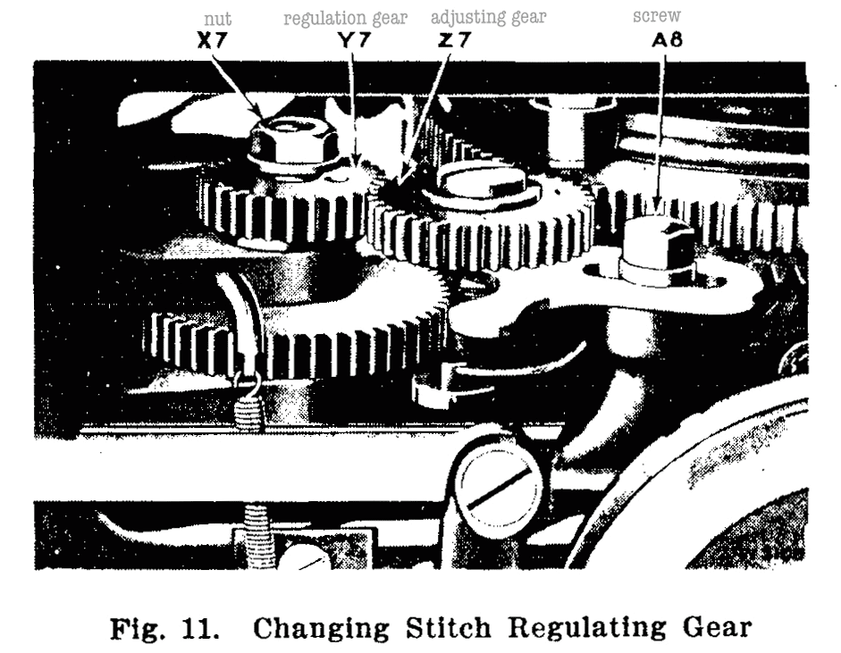
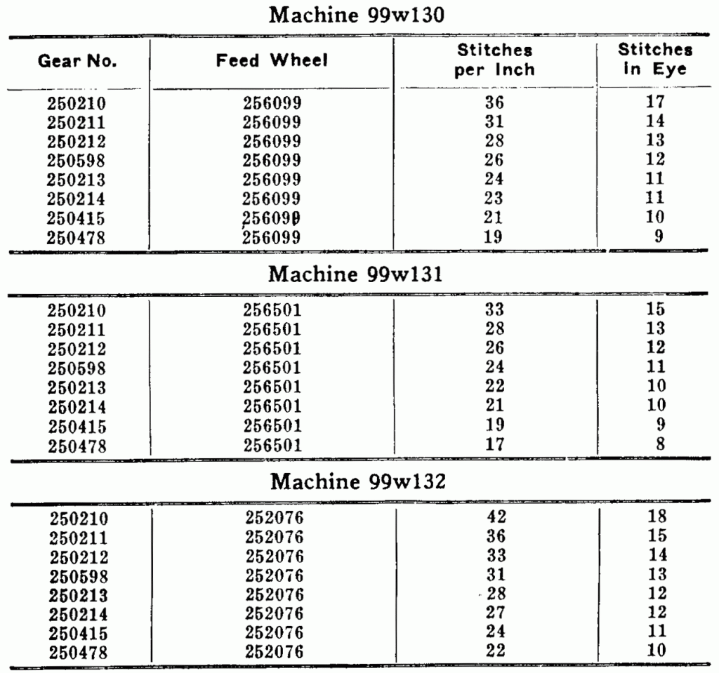
¶ The number of stitches in the buttonhole is controlled by the stitch regulating gear (Y7, Fig. 11) in the left side of the machine. ¶ When it is desired to change the number of stitches in the button- hole it will only be necessary to change the stitch regulating gear. ¶ To remove this gear, loosen the screw (A8, Fig. 11) in the slotted lever and pull the lever toward you, then remove the nut (X7, Fig. 11) which is above the stitch regulating gear (Y7, Fig.11) and lift off the gear with the stitch regulating gear holder. ¶ The stitch regulating gears are listed below:Having selected the gear desired, place it in position and firmly fasten it with nut (X7, Fig. 11). ¶ Then advance the pattern wheel shaft by means of wrench a slight amount and at the same time push on the end of feed adjusting gear bracket until the adjusting gear (Z7, Fig. 11) drops into mesh with the stitch regulating gear. After the gears have been correctly set, tighten the screw (A8, Fig. 11). ¶ When turning the pattern wheel shaft with the wrench, care should be taken that it is turned only sufficiently far to mesh the first tooth, thus avoiding moving the machine out of cutting position.
Stitch Regulating Gears
To Oil the Machine
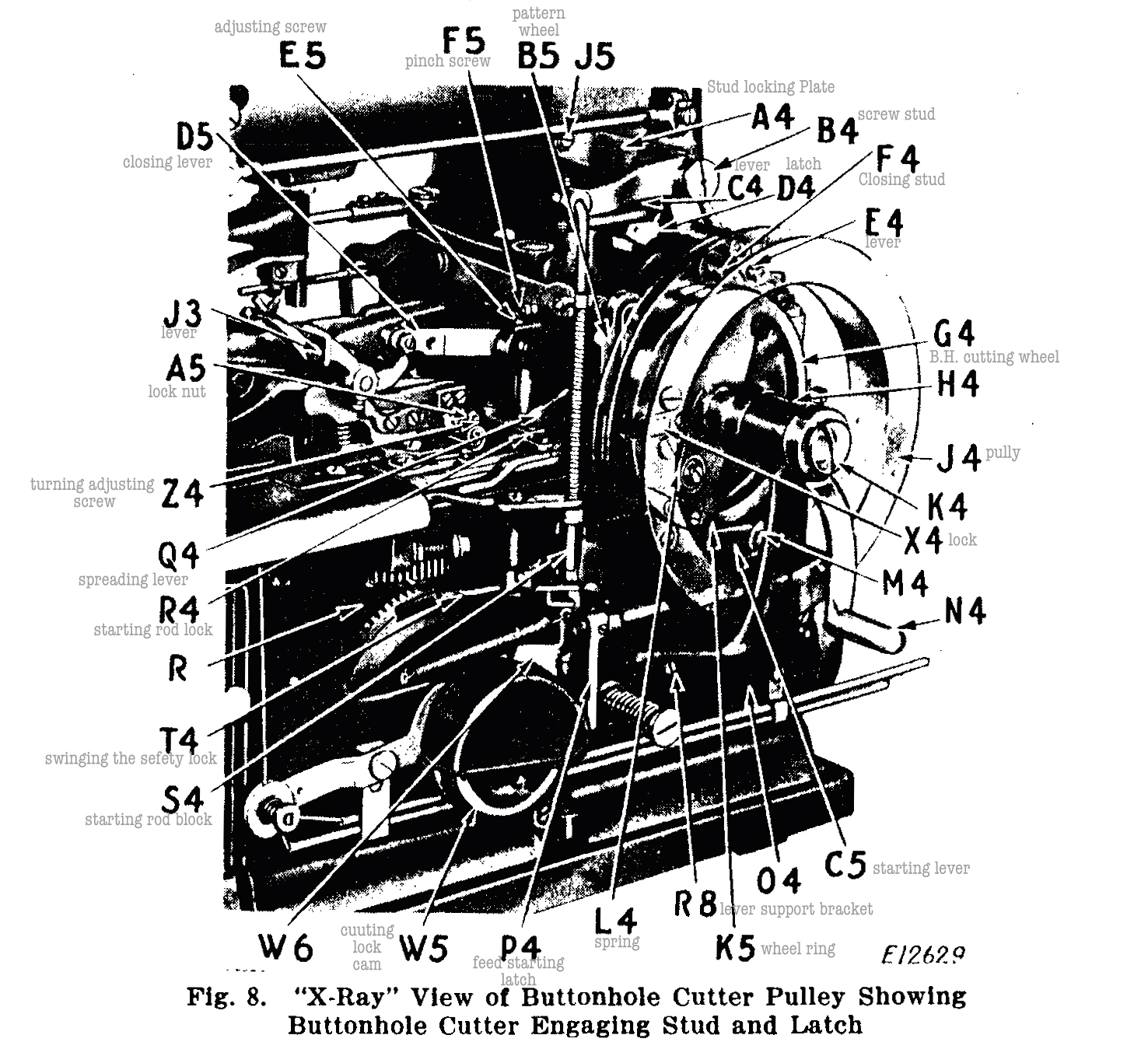
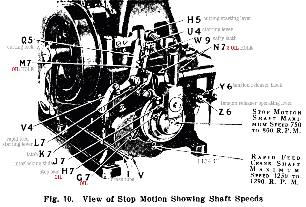
¶ To ensure easy running and prevent unnecessary wear to the machine, oil should be regularly applied at least once each day to all oil holes and all parts which are in movable contact. ¶ Oil should be applied to the two oil holes (C and N, Fig. 2) for the arm shaft bearings located on the top of the front and rear of the arm; also to the oil hole (P9, Fig. 2) in the top end of the needle thread take-up shaft for the shaft bearing. The take- up lever and cam should be oiled through the left side of the take- up bracket at D8, Fig. 36. ¶ The needle vibrating lever and the upper bearing for the vertical shaft should be oiled through the opening (L8, Fig. 36) at the upper left rear end of the arm. ¶ All connections of the upper stitch rotating mechanism should have oil applied to all movable parts. ¶ Oil should be applied to the needle vibrating connections on the right side of the arm and all parts connected to this mechanism located on the lower end of the needle bar; also applied through the oil hole (L, Fig. 2) in the arm face plate to the needle bar and its connections. ¶ At the back end of the machine, oil should be applied through the opening (F6, Fig. 9) to the roller way of the cutter carrier cam and its connection, to the cutting lever cam seat, to the buttonhole cutting lever cams and to the lower bearing for the vertical shaft. ¶ Oil should be applied to the oil tube (M7, Fig. 10) for the bed shaft bushing, to the oil tube (C6, Fig. 9) for the rapid feed crank shaft rear bearing and to the oil hole (G7, Fig. 10) in the end of the rapid feed intermediate gear stud. ¶ Oil should be applied to the two oil holes (N7, Fig. 10) in the stop lever bracket as well as to the stop cam (H7, Fig. 10) and all sliding surfaces of the interlocking slide (J7, Fig. 10) located at rear end of the bed. ¶ Through the opening (P5, Fig. 9) in the left hand side of the bed, oil should be applied to the feed wheel cam paths, to the lower stitch rotation connections, to the hinge stud for the lower sector and to the oil holes for the bearings located on the left edge of the bed for the pattern wheel shaft and slide bar. ¶ Oil should be applied to the oil pad for the rapid feed starting pawl (K6, Fig. 9) located immediately above the pawl inside the left edge of the bed and to all movable parts of the rapid feed tripping mechanism located within the bed. ¶ The cam groove of the pattern wheel (U5, Fig. 9) and the operating surface of the pattern wheel ring (R5, Fig. 9) should be oiled; also the connections from it to the stop lever and to the side throw lever. ¶ Oil should be applied to the oil tube (05, Fig. 9) for the front bed shaft bearing. ¶ After removing the bed end cover (T3, Fig. 6) oil should be applied to all movable parts of the looper mechanism, and to the slide block (P2, Fig. 3) on the forward end of the side throw lever. ¶ Oil should be applied to the movable parts on the work plates (03 and W3, Fig. 6); that is, to the clamp arm cams, shafts and hinge blocks; also to the two oil holes (Q3 and V3, Fig. 6) in the forward end of each plate which carry oil to the base plate slide rod (Q2, Fig. 3). ¶ Swing each work plate (03 and W3, Fig. 6) out and apply oil to the oil hole in the left side of the base plate immediately above oil hole (S2, Fig. 38) for the side throw lever shaft; also apply oil to the looper mechanism, to the feed wheel cam paths, to the left and right clamp carrier slides and to the oil hole (U2, Fig. 5) for the feed wheel axis stud located beneath the cutting levers in the cutting lever bracket. ¶ Insert the tip of the oil can into the forward right hand open- ing (R, Figs. 3 and 8) in side of the bed and apply oil to the forward bearing (Z, Fig. 3) of the rapid feed crank shaft and apply oil to the oil holes for the pattern wheel shaft and slide bar located on the lower edge of this opening. ¶ Oil should be applied to the hinge stud (L3, Fig. 3) for the clamp closing lever (D5, Fig. 8), to the engaging stud (F4, Fig. 8) and latches connected to the operation of this mechanism as well as to all movable parts connected with the starting mechanism. ¶ Oil should be applied to the two oil holes for the buttonhole cutting shaft, to the oil cup in the hub of the cutting shaft pulley (J4, Fig. 8), to the oil hole (H4, Fig. 8) in the support for the right hand end of cutting shaft and to the hole in the head of the hand crank cap screw (K4, Fig. 8) on the right end of the cutting shaft. ¶ It is extremely important that the oiling of the machine be carried out diligently each day, using SINGER “Oil for High Speed Sewing Machines (Cloth and Leather)” for general use or “Stainless Oil for High Speed Sewing Machines” where a stain- less oil is desired. ¶ This will be an investment that will yield exceptional returns as it will reduce the demand for service as well as reduce the cost of upkeep and will greatly increase the life of the machine.
