ミシン71-30~71-47用の針は、クラスおよび種類71 x 1(サイズ11、13、14、16、18、19、21)と71 x 3(サイズ11、13、14、16、18)があります。 使用する針のサイズは、針穴をスムーズに通る糸の太さによって決定してください。粗い糸や不均一な糸を使用したり、糸が針穴を通りにくい場合は、ミシンの正常な動作が妨げられます。 針のご注文の際は、必要な数量、サイズ番号、およびクラスと種類番号をXで区切って明記してください。以下は、分かりやすい注文例です。 「100本 No.16、71 x 1 針」 「100本 No.14、71 x 3 針」 最高の縫製結果を得るには、シンガーミシン会社が提供する針を使用することをお勧めします。
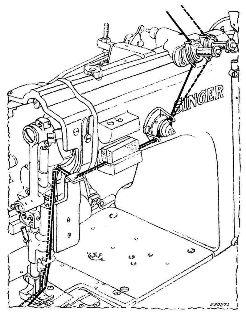
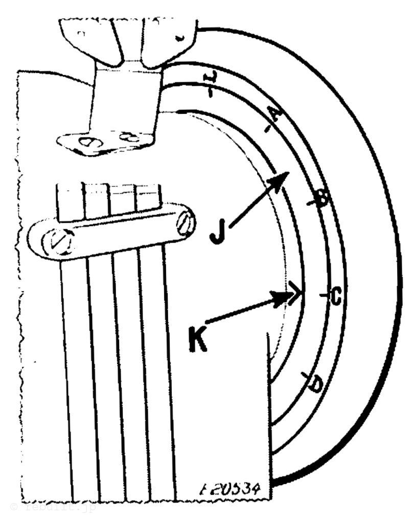
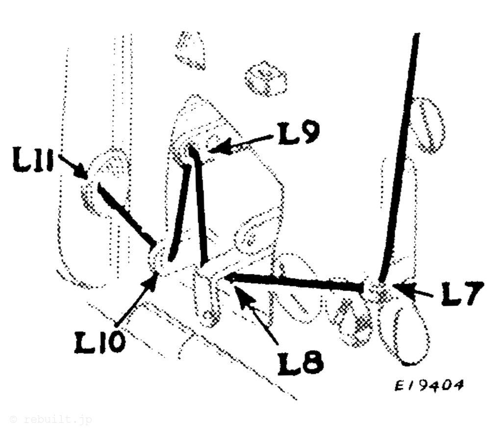
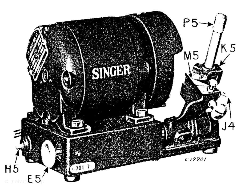
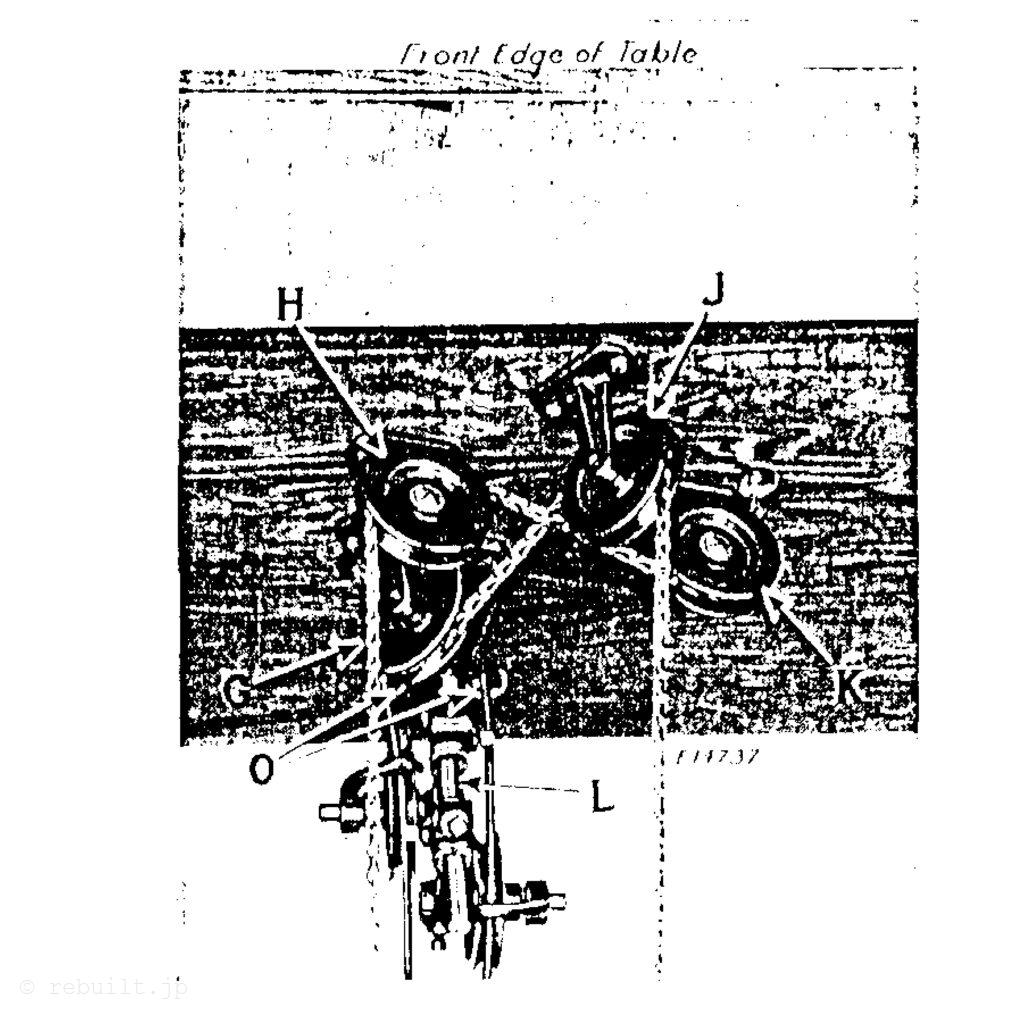
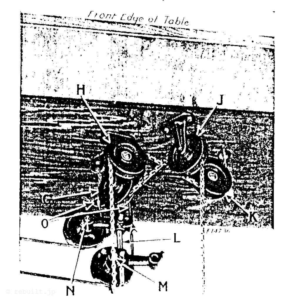
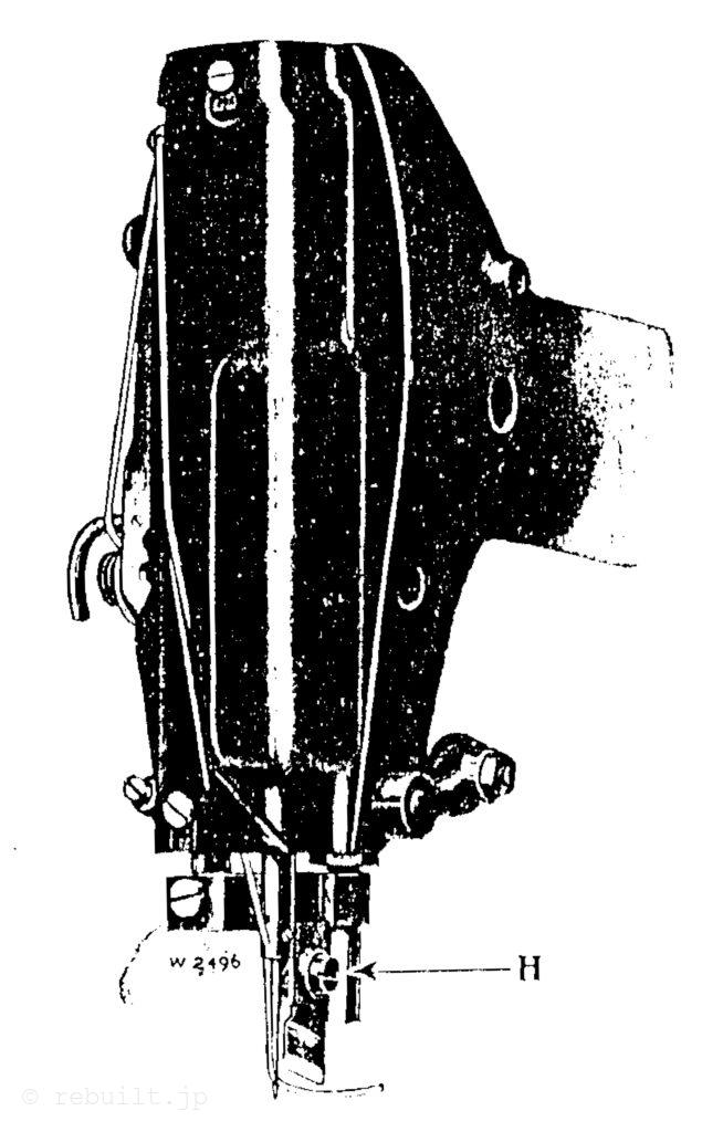
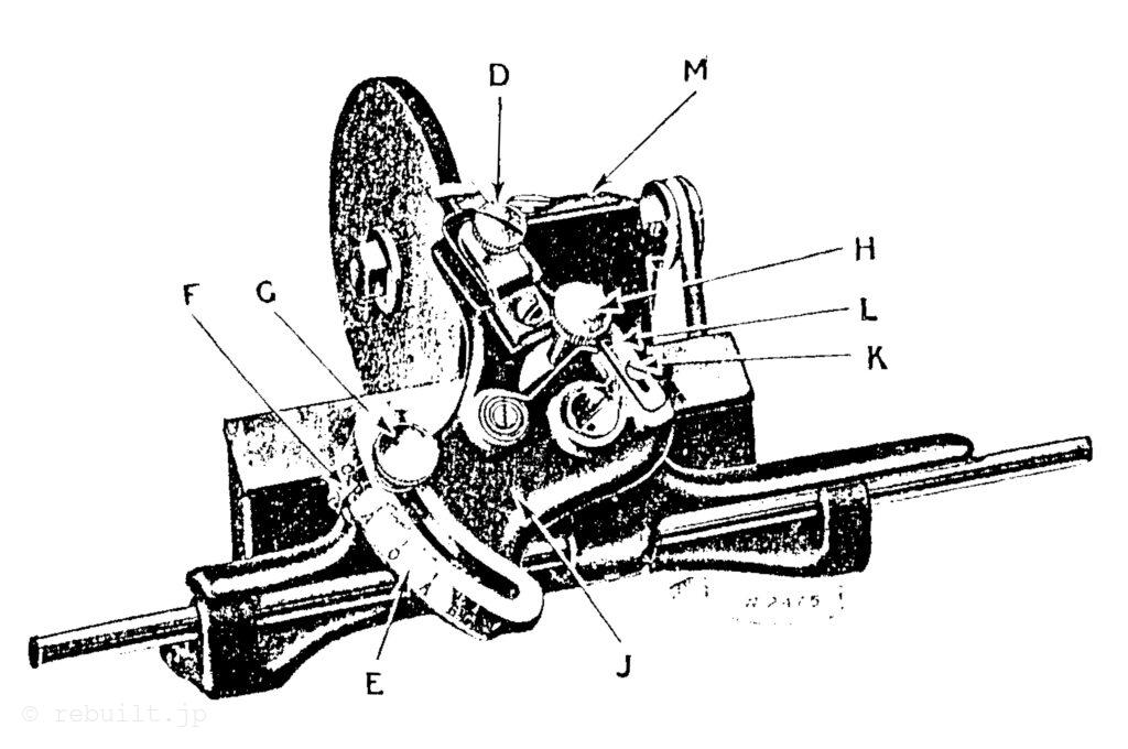
A. 針糸の張力を調整するつまみナット。 B. 針棒とナイフの位置を合わせるネジ。 C. ナイフを動作から外すレバー。 D. 針糸張力調整ディスク。 E. クランプを動かす手動ラチェットレバー。 F. ボタンホールの長さを調整するレバーを覆うスライド。 G. ミシンを停止させるレバー。 H. 切断幅を調整するネジ。 I. ナイフレバー。 J. ナイフバー駆動レバー。 K. ナイフバークランプ。 L. ナイフバー駆動レバースプリング。
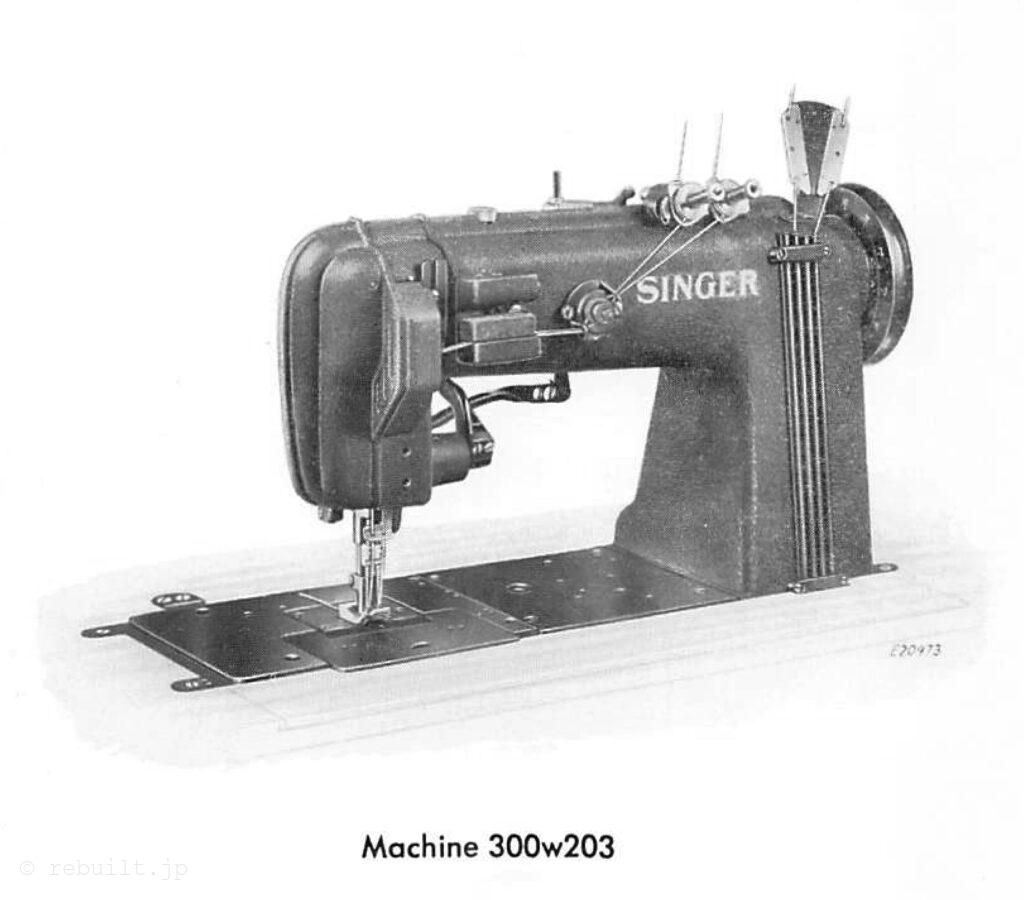
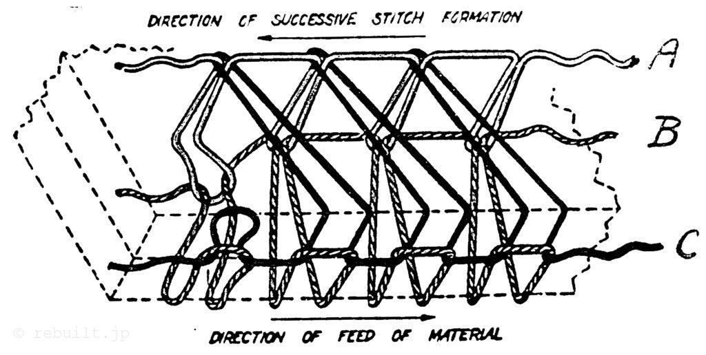
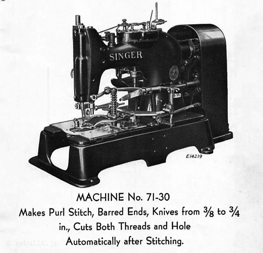
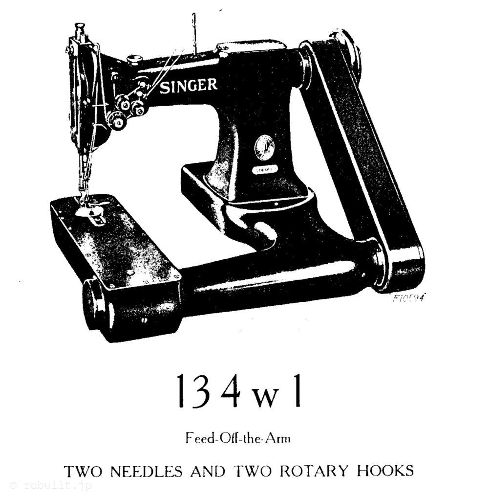
DESCRIPTION Machine 134w1, feed-off-the-arm, is used for lap seam felling on men’s shirts, underwear, pajamas, overalls and other tubular work. It can also be used for inserting the sleeves in shirts and pajamas. It has two needles and two rotary sewing hooks and simultaneously makes two parallel lines of lock stitching. The gauge or distance between the two needles may be from inch to inch, in steps of 1⁄2 inch, as desired. When ordering, state the gauge required and furnish sample of material to be used.
Speed The machine should be driven at a speed not exceeding 3500 revolutions per minute for the first two or three days, after which it can be driven up to its maximum speed of 4000 revolutions per minute, depending on the nature of the work and the ability of the operator. When the machine is in operation, the top of the balance wheel must turn toward the operator.
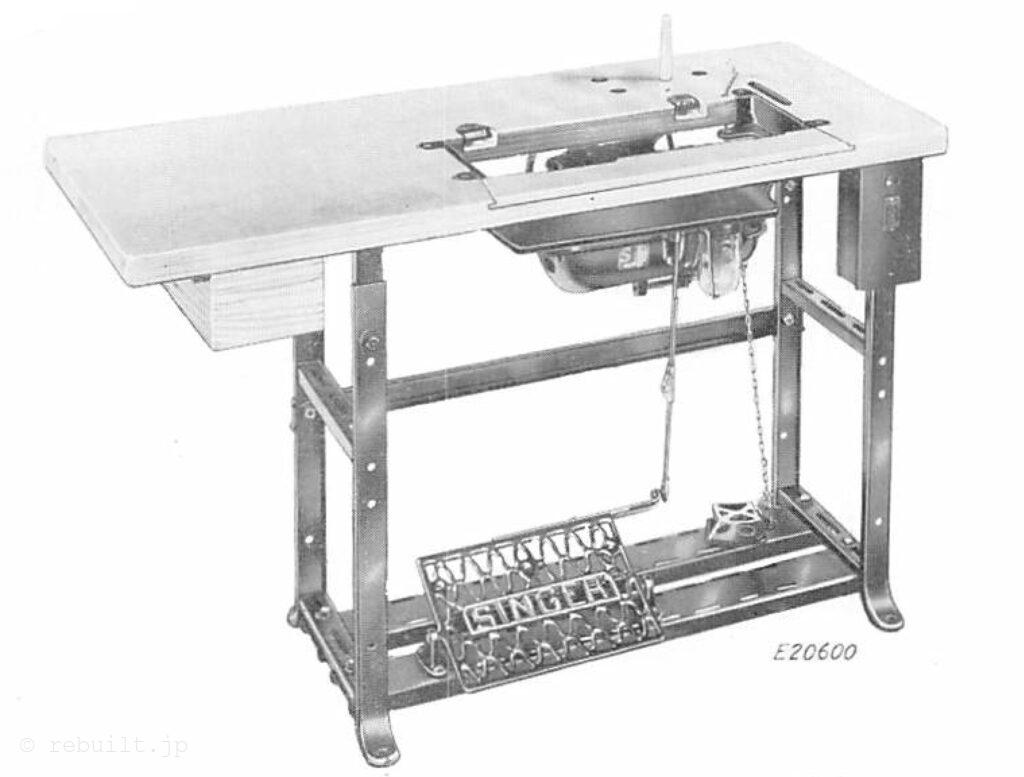
To Set Up the Machine Follow the instructions given in Form 2320w.
CAUTION: After setting up, do not start the machine, not even to test the speed, until it has been thoroughly oiled, as instructed on pages 4 and 5.
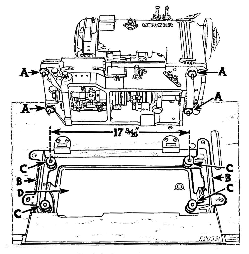
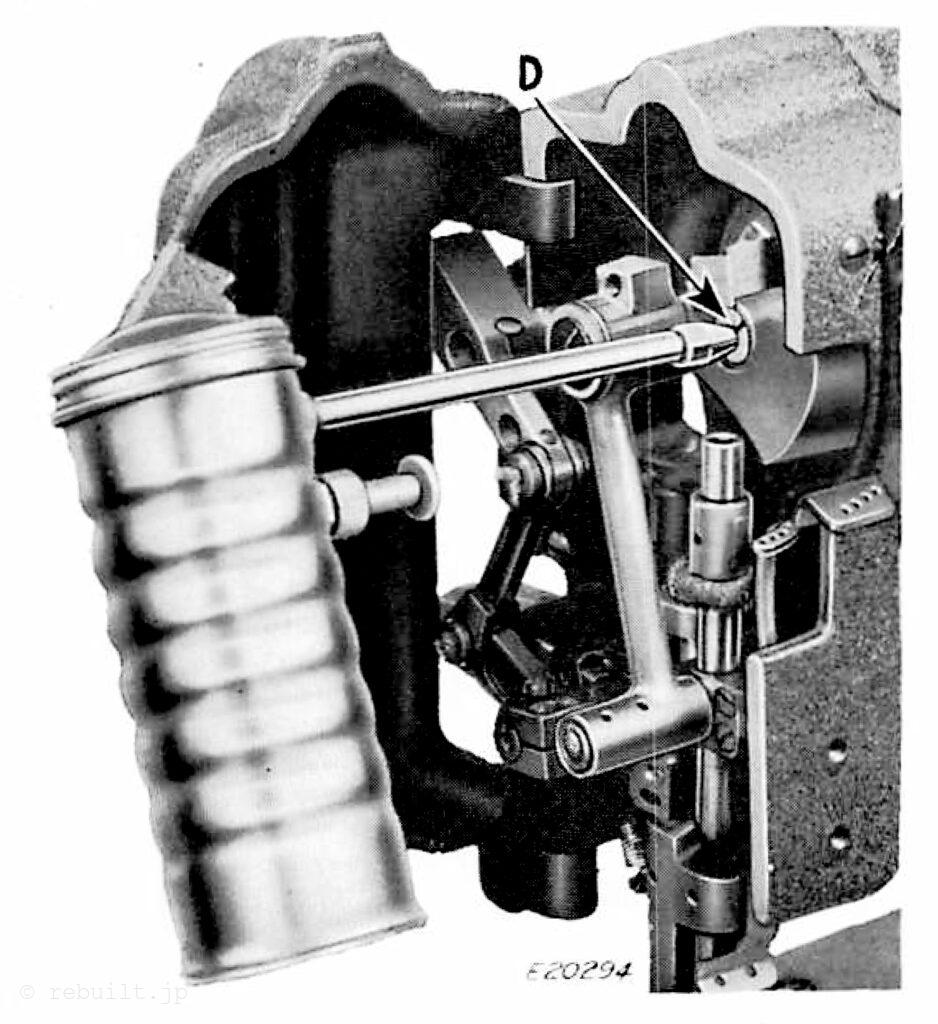
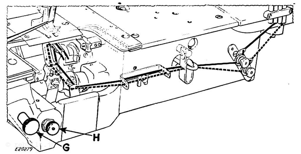
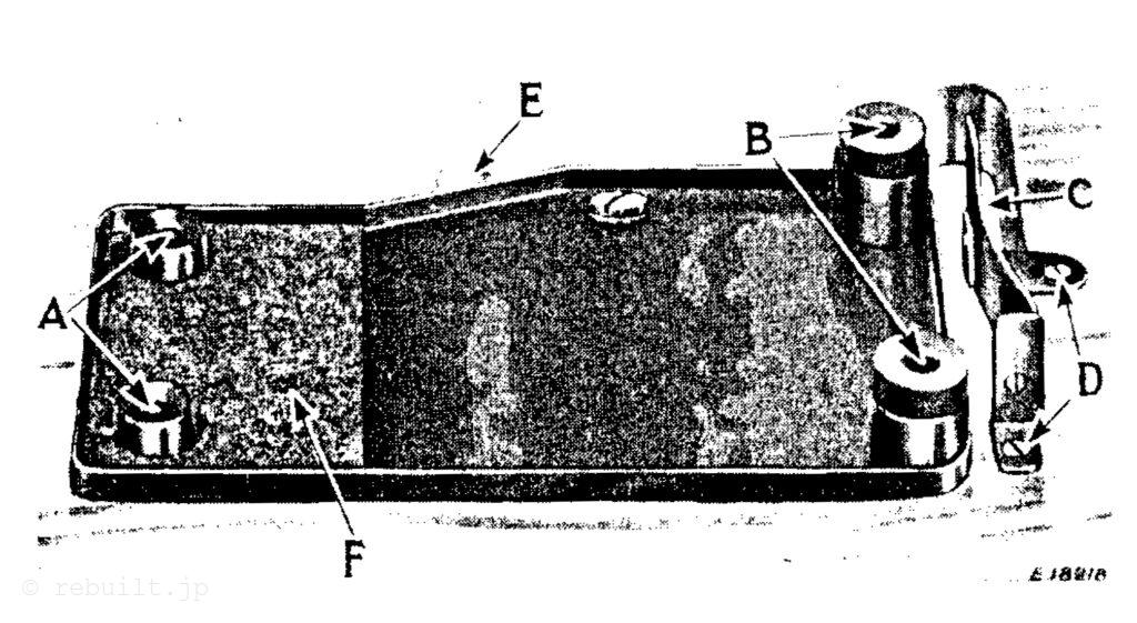
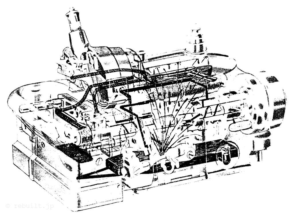
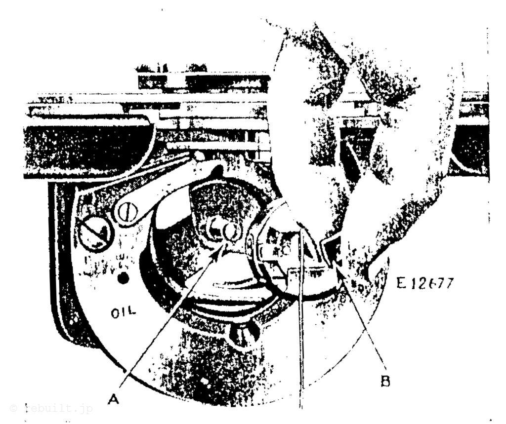
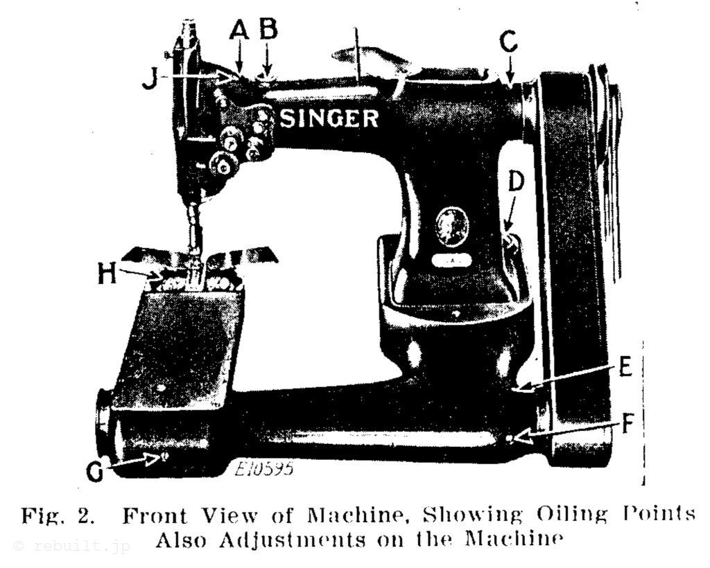
オイル排出。機械から出る余分なオイルは、図 2 の D で示すように、機械の背面のベースにあるオイル ウェルに排出されます。このオイル ウェルは、乾いた布でオイルを吸い取ることで空の状態に保つことができます。
To Oil the Machine Use only “Singer Manufacturing Sewing Machine Oil (Stain- less for White Goods)” for the lubrication of this machine. All of the oil is drained out of the machine before it is shipped from the factory, therefore it is absolutely necessary that the machine be thoroughly oiled according to the following instructions before it is started in operation:
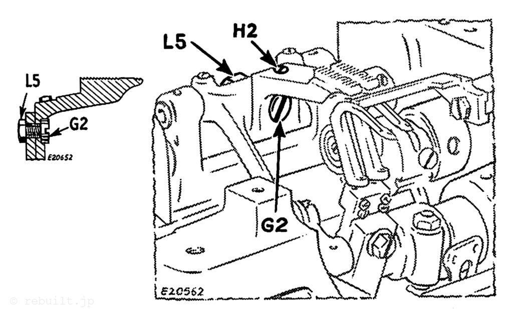
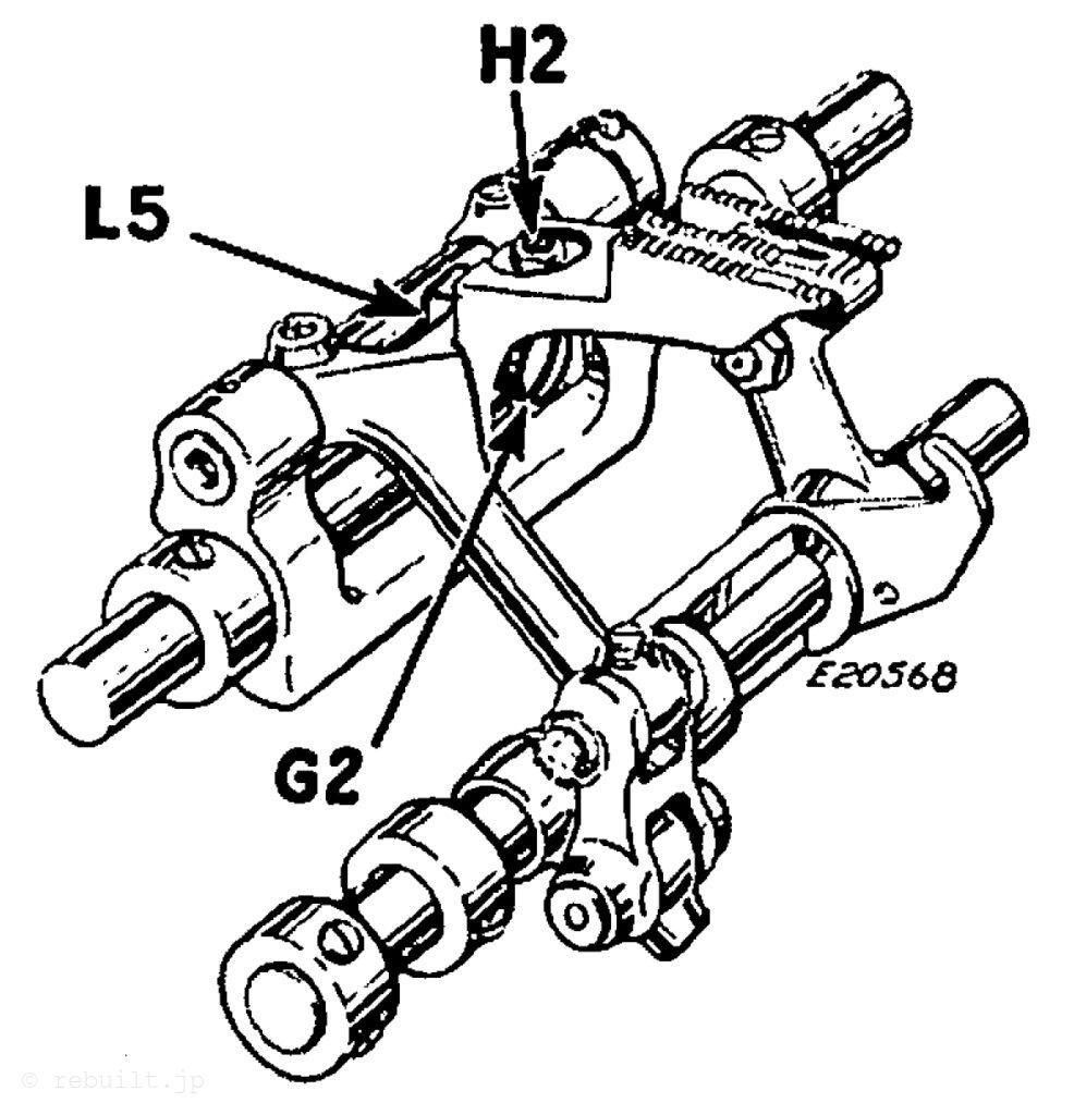
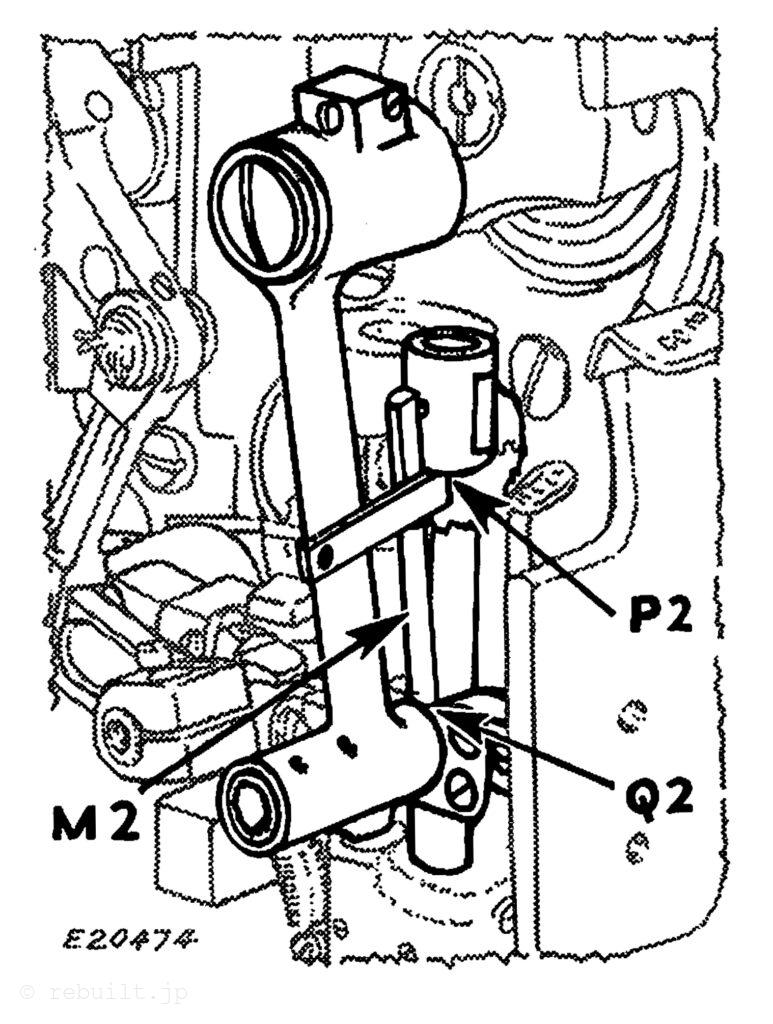
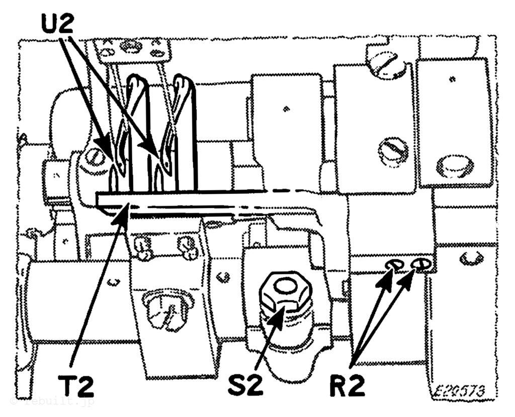
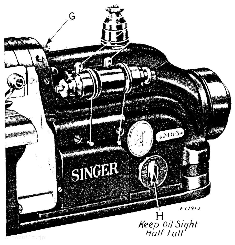
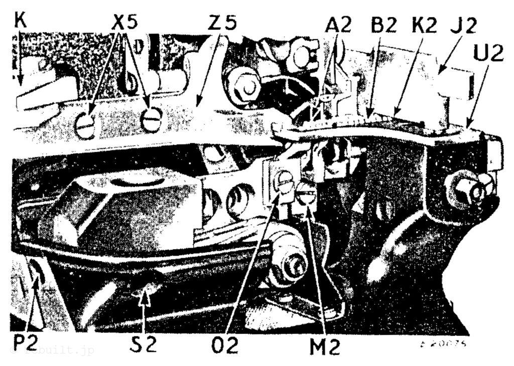
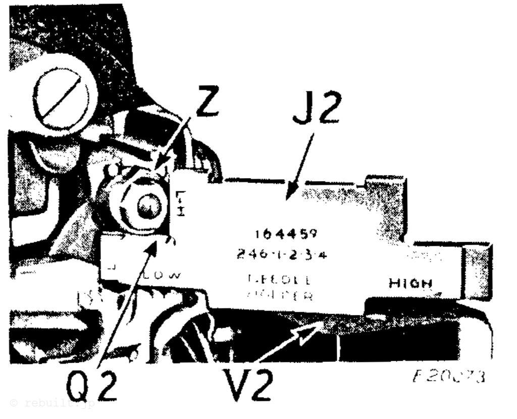
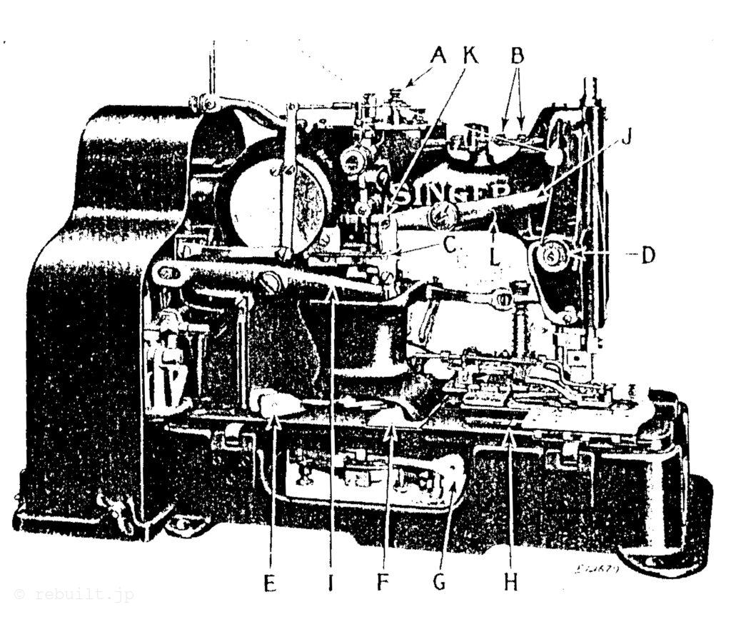
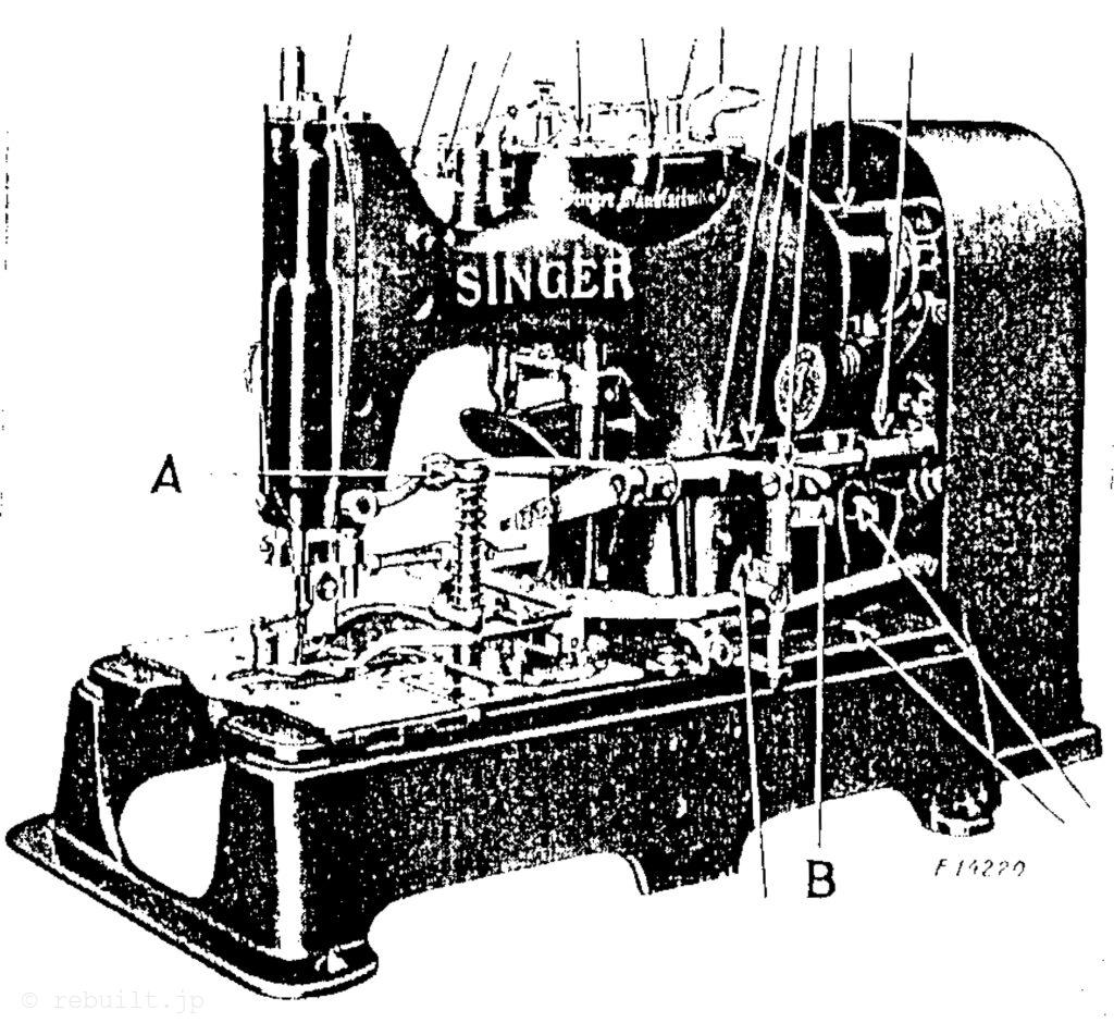
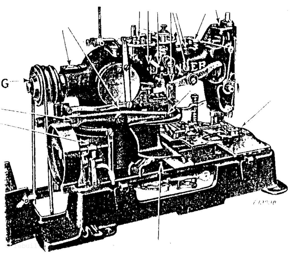
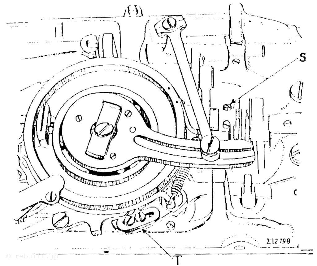
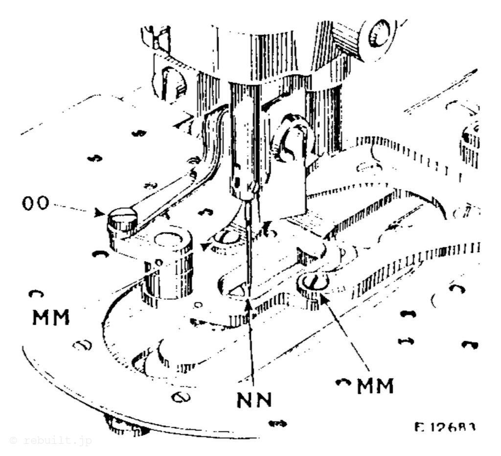
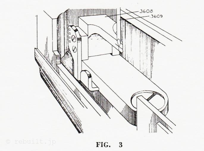
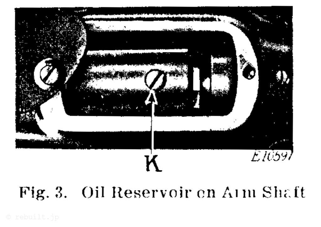
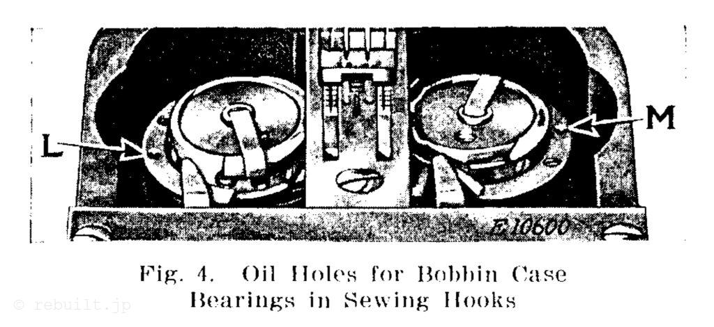
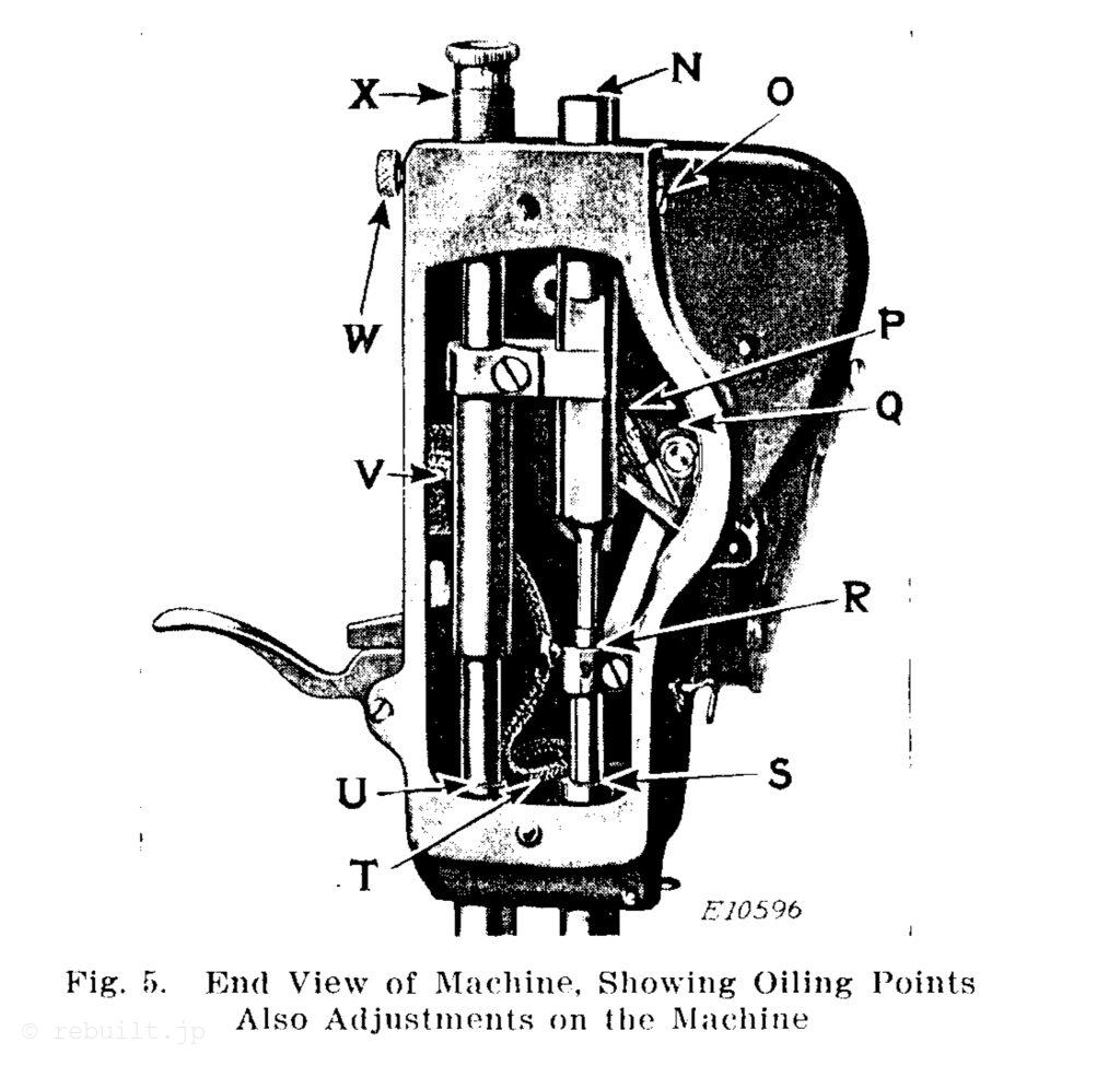
1. After the machine has been set up so that its bed cover plate is perfectly level, remove the screw plug (G, Fig. 2), then swing back the hook covers and pour oil into the bed through the opening (H, Fig. 2) until it starts to flow out of the screw plug hole at (G), then replace the screw plug tightly. This hole indicates the high level of the oil which should be maintained in the bed. This oil level must be checked once each week when the machine is in continuous use. 2. Remove the screw plug (K, Fig. 3) which is located in the revolving oil reservoir in the arm of the machine and completely fill the reservoir, then replace the screw plug (K) tightly. The oil flows from this reservoir through the hollow arm shaft to lubricate the needle bar and thread take- up driving mechanism in the arm head. This oil reservoir must be filled once each week, when the machine is in continuous use. 3. Using the oil can furnished with the machine, apply oil to the places marked (A, B and C, Fig. 2), (L. and M, Fig. 4) and (N, P, Q, R, S, T, U and V, Fig. 5). These points must be oiled daily when the machine is in continuous use, except the places marked (L and M, Fig. 4) which must be oiled each time a bobbin is replaced. Oil Drain. Surplus oil from the machine drains into the oil well which is located in the base of the machine at the rear, as shown at D, in Fig. 2. This oil well may be kept empty by soak- ing out the oil with a dry rag.
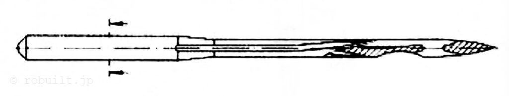
Needles Needles for Machine 134w1 are of Class and Variety 128×13 and are made in sizes 12, 13, 14, 16, 18 and 20. The size of the needles to be used should be determined by the size of the thread, which must pass freely through the eye of the needles. If rough or uneven thread is used or if it passes with difficulty through the eye of the needles, the successful use of the machine will be interfered with. Use smooth finish thread. Orders for needles must specify the quantity required, the size number, also the class and variety numbers separated by the letter X.
The following is an example of an intelligible order: 100 Size 14. 128×13 Needles.” The best results will be obtained in using the needles furnished by the Singer Sewing Machine Company.
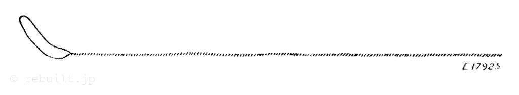
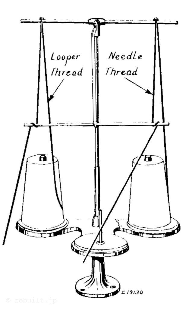
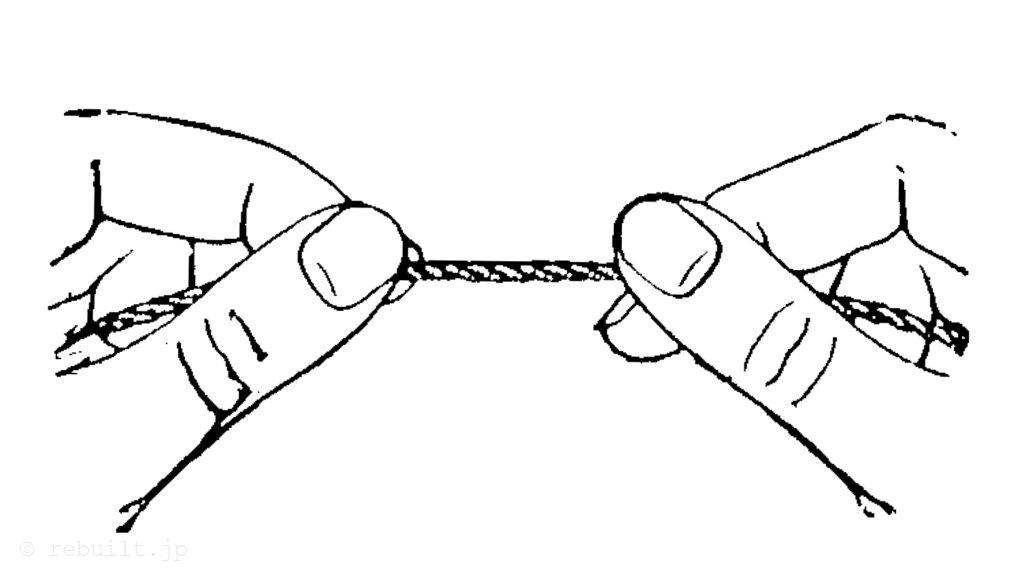
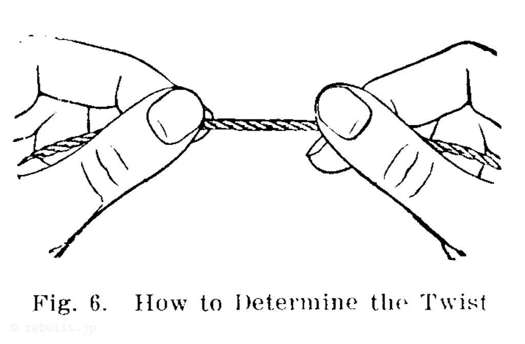
Thread Use left twist thread for both needles. Either left or right twist thread may be used for the bobbins. Hold the thread as shown above. Turn the thread over toward you between the thumb and the forefinger of the right hand; if left twist, the strands will wind tighter; if right twist, the strands will unwind.
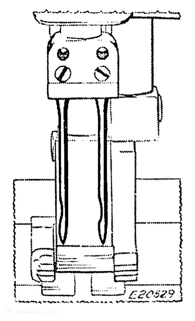
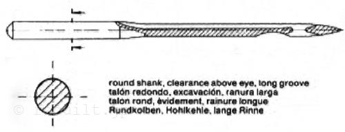
To Set the Needles Loosen the set screws in the needle holder and put the needles up into the holder as far as they will go, with the long grooves of the needles facing each other, then securely tighten the set screws.
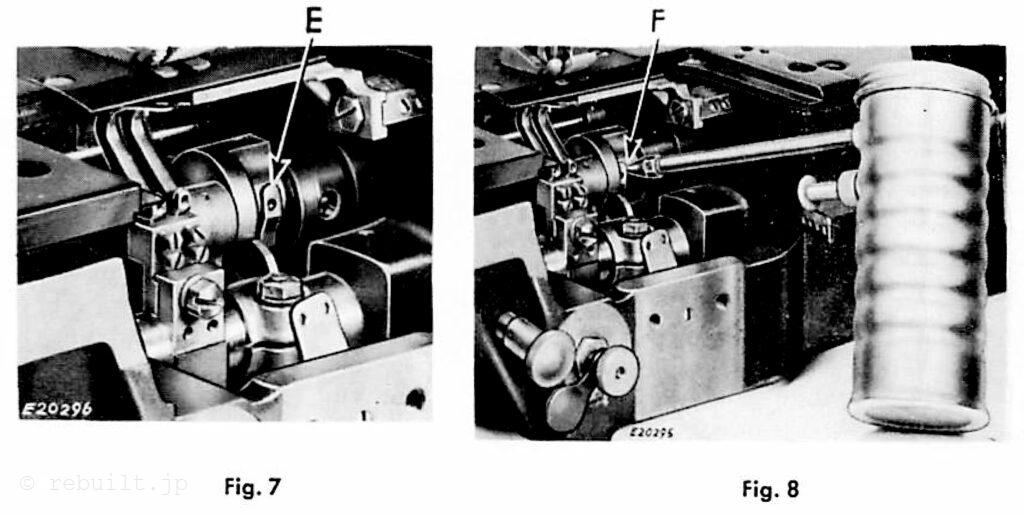
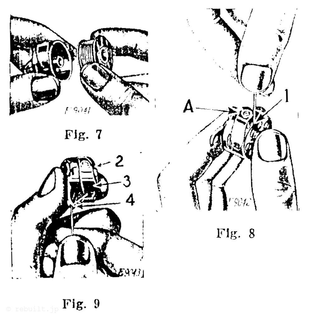
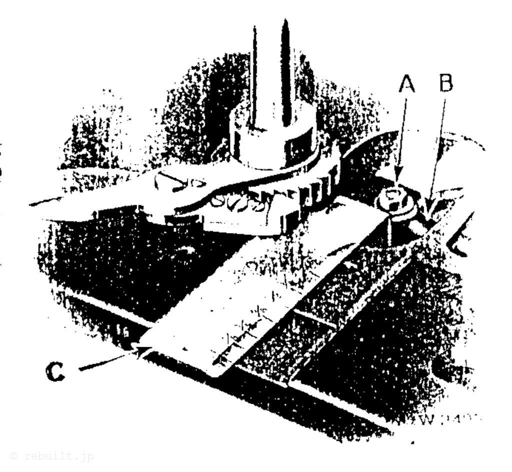
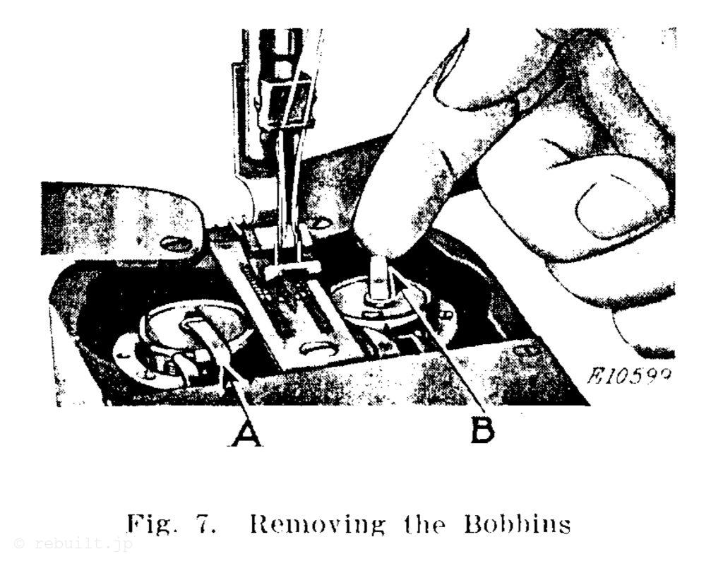
To Remove the Bobbins Swing back the hook covers at the end of the bed. Insert the finger nail of the forefinger under the latches (A and B, Fig. 7). raise the latches, then lift out the bobbins. Ready wound cops can also be used.
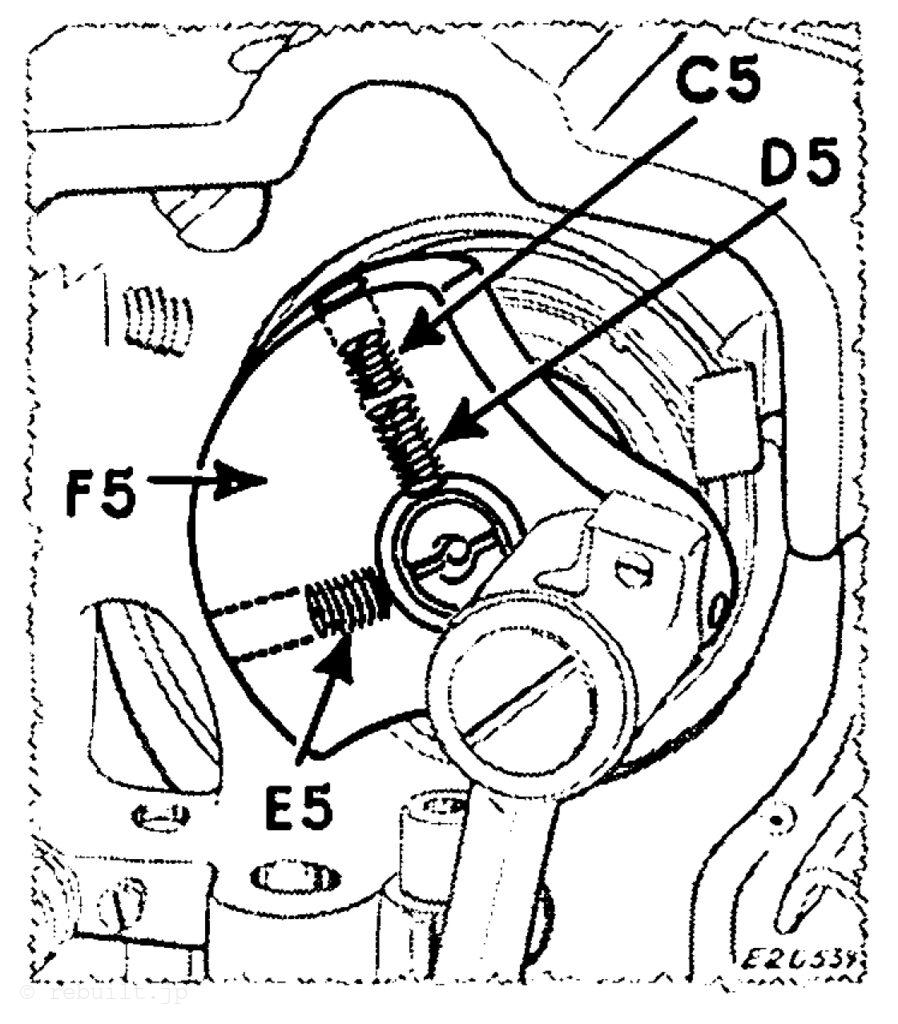
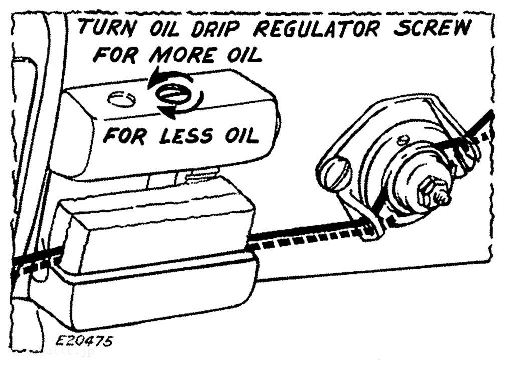
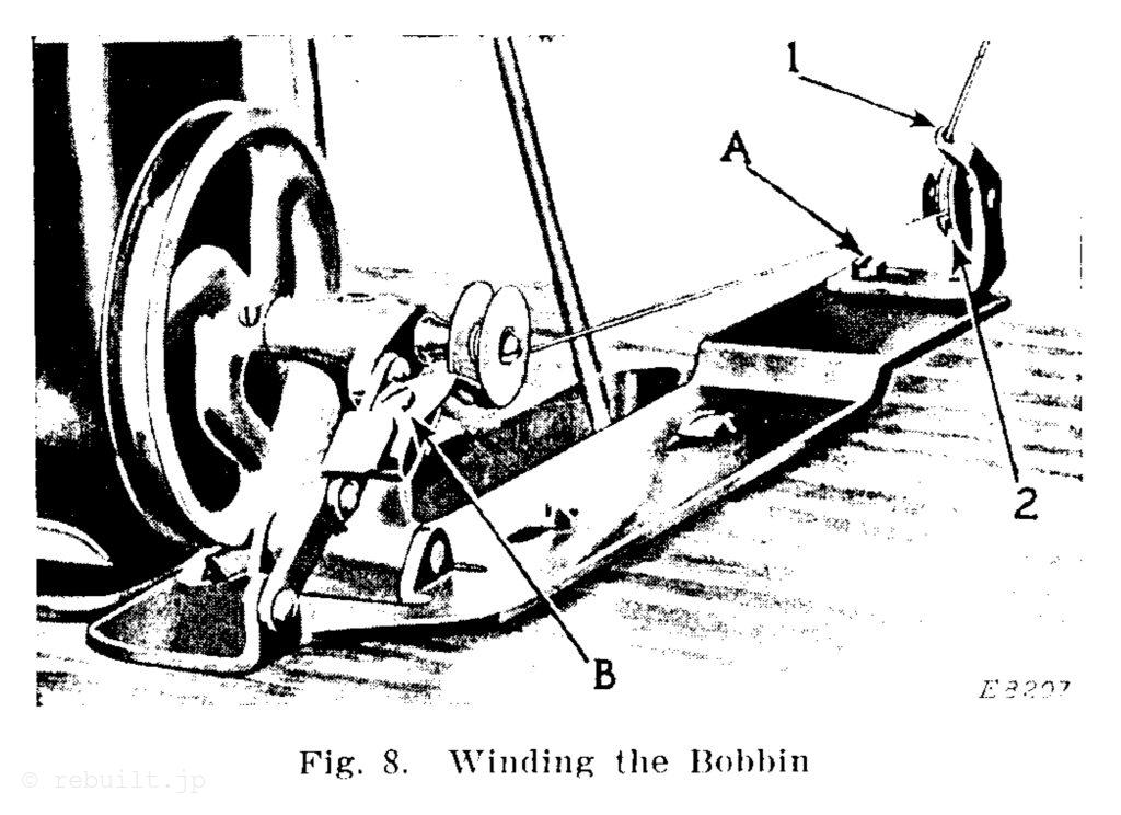
To Wind the Bobbin (See Fig. 8) Fasten the bobbin winder to the table with its driving pulley in front of the machine belt, so that the pulley will drop away from the belt when sufficient thread has been wound upon the bobbin. Place the bobbin on the bobbin winder spindle and push it on as far as it will go. Pass the thread down through the thread guide (1) in the tension bracket, around the back and between the tension dises (2). Then wind the end of the thread around the bobbin a few times, push the bobbin winder pulley over against the machine. belt and start the machine. When sufficient thread has been wound upon the bobbin, the bobbin winder will stop automatically. If the thread does not wind evenly on the bobbin, loosen the screw (A) in the tension bracket and move the bracket to the right or left as may be required, then tighten the screw. The amount of thread wound on the bobbin is regulated by the screw (B). To wind more thread on the bobbin, turn the screw (B) inwardly. To wind less thread on the bobbin, turn the screw outwardly. Bobbins can be wound while the machine is stitching.
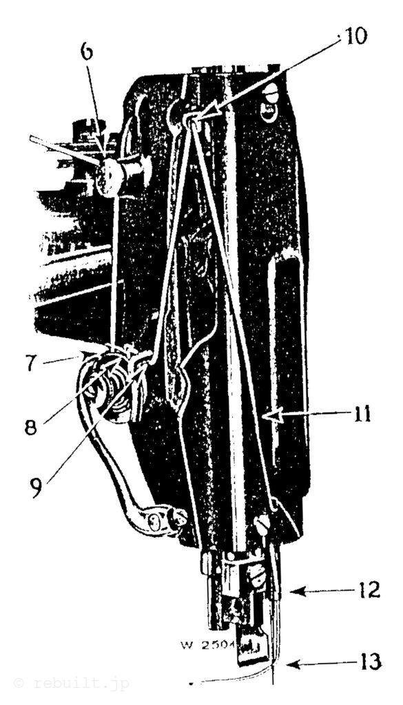
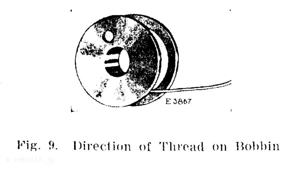
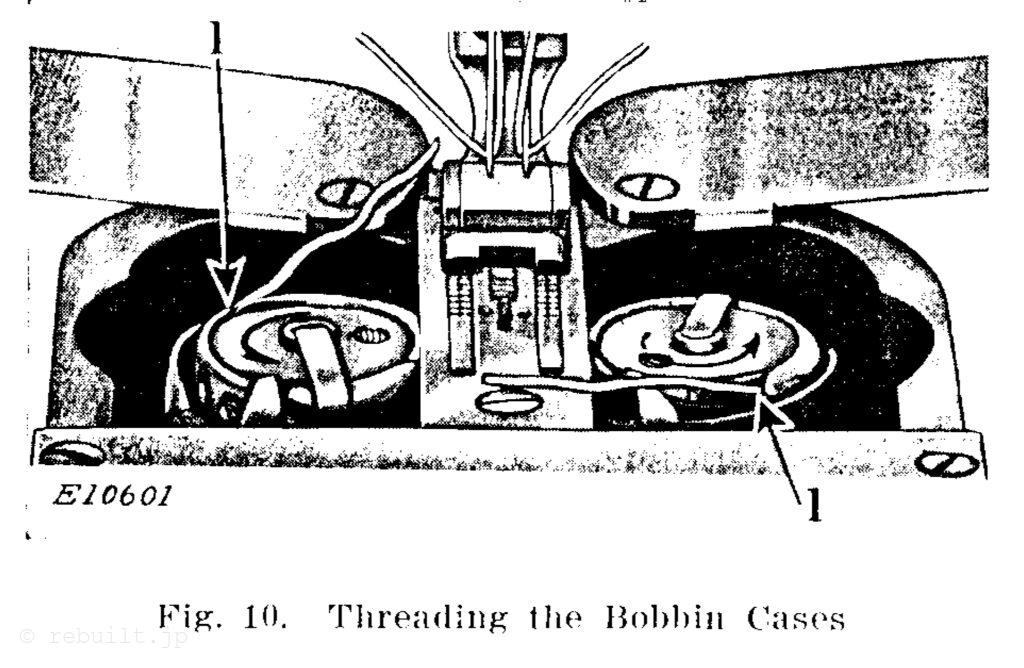
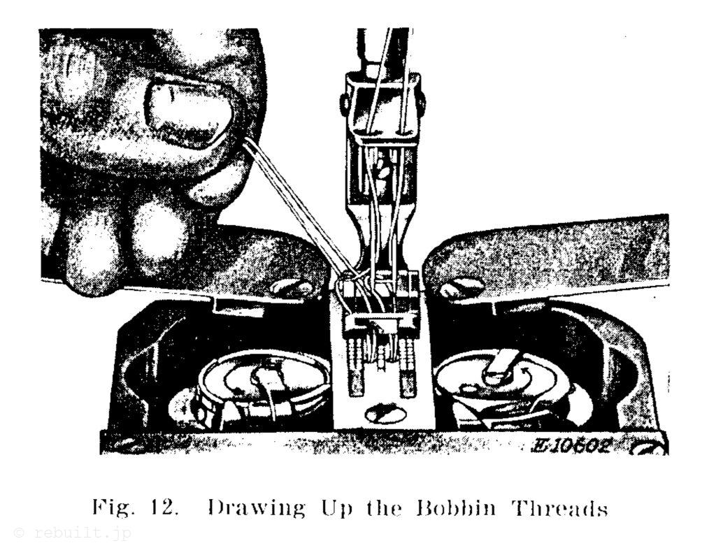
To Replace the Bobbins and Thread the Bobbin Cases The following instructions apply to both bobbin cases: Hold the bobbin between the thumb and forefinger of the right hand, the thread drawing on the bottom from left to right (see Fig. 9) and place it on the centre stud of the bobbin case, then push down the latch, as shown in Fig. 10. Draw the threads into the slot (1, Fig. 10) and towards the presser foot, as shown in Fig. 10, leaving a loose end of thread about two inches long above the hook covers. Do not close the hook covers tight until the bobbin threads have been drawn up by the needle threads, as shown in Fig. 12. Apply oil to the oil holes (L and M, Fig. 4) in the hook gibs each time a bobbin is replaced.
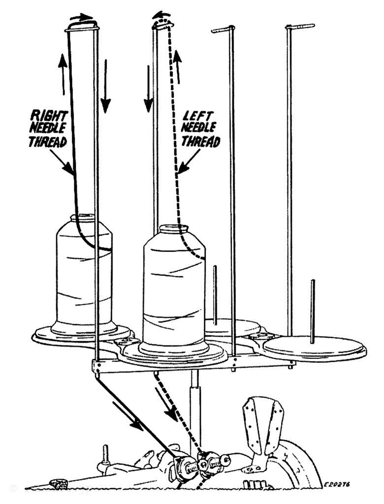
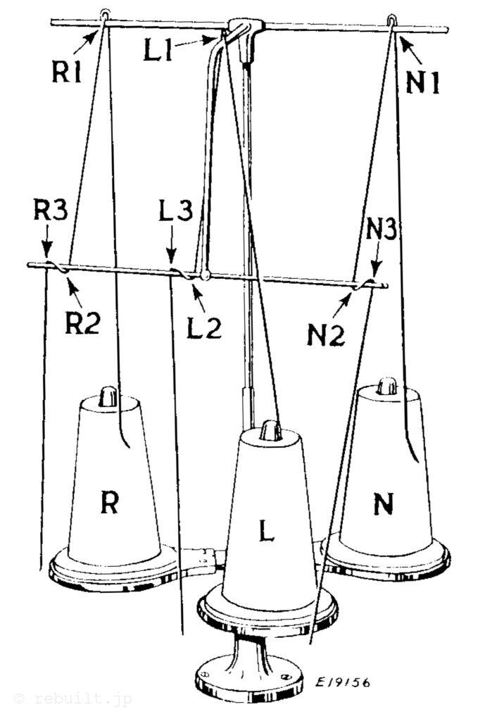
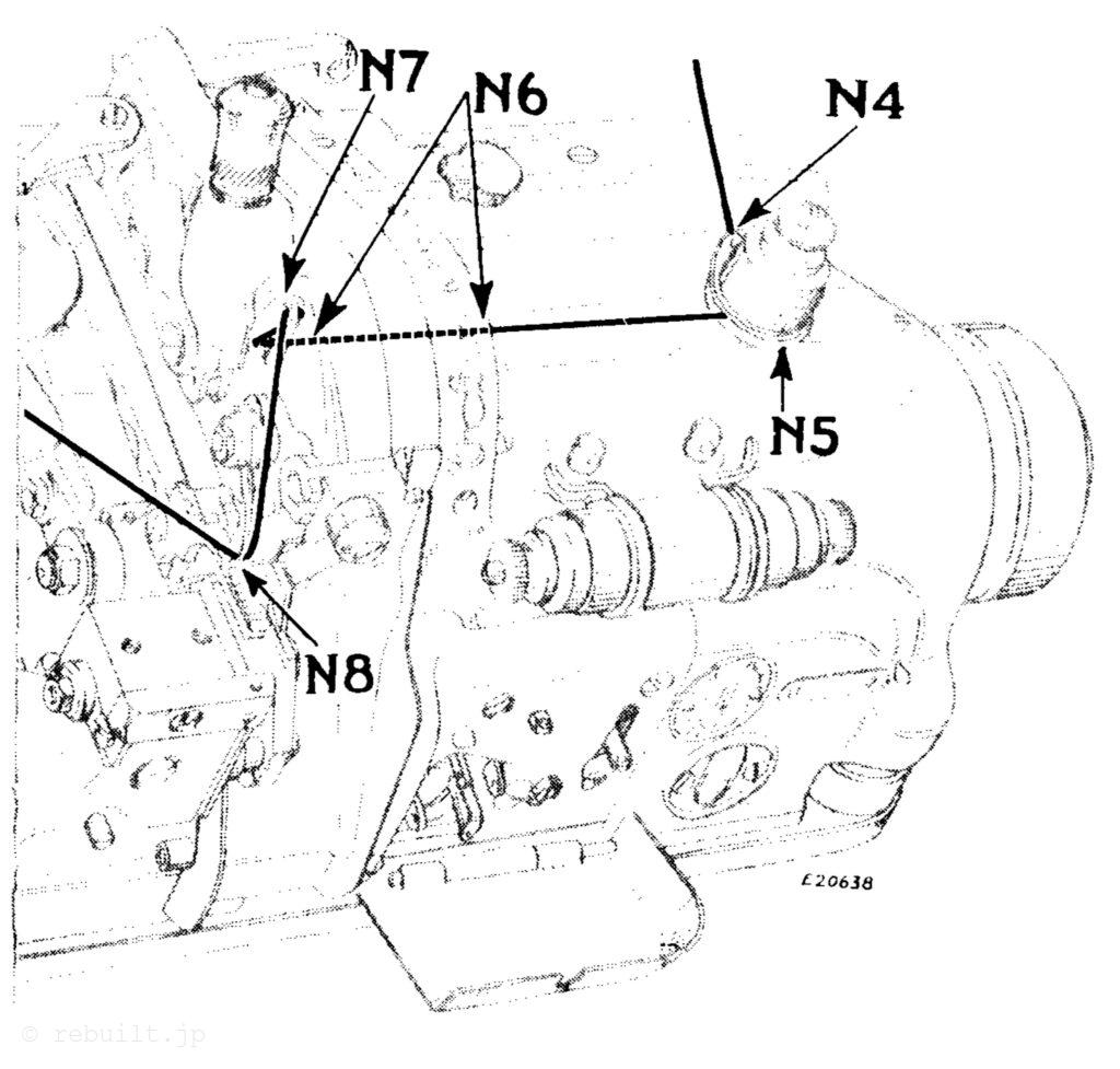
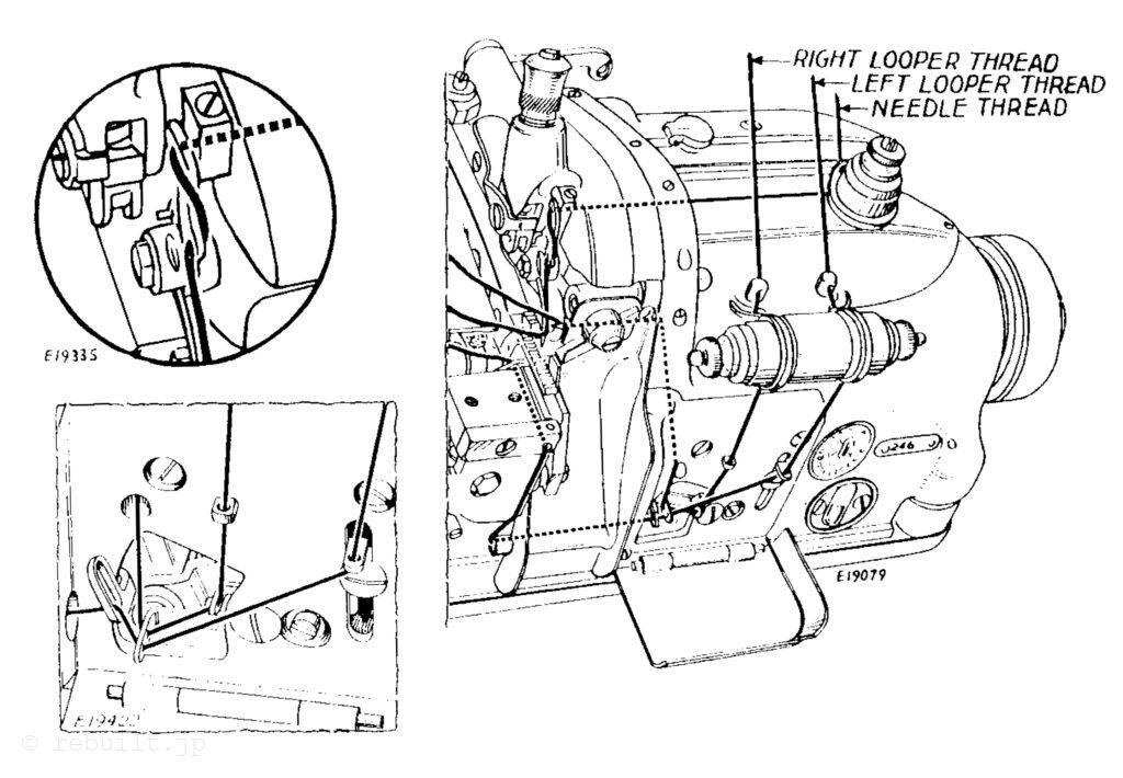
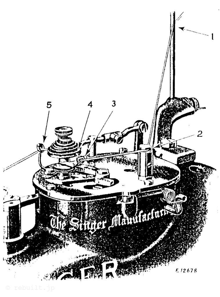
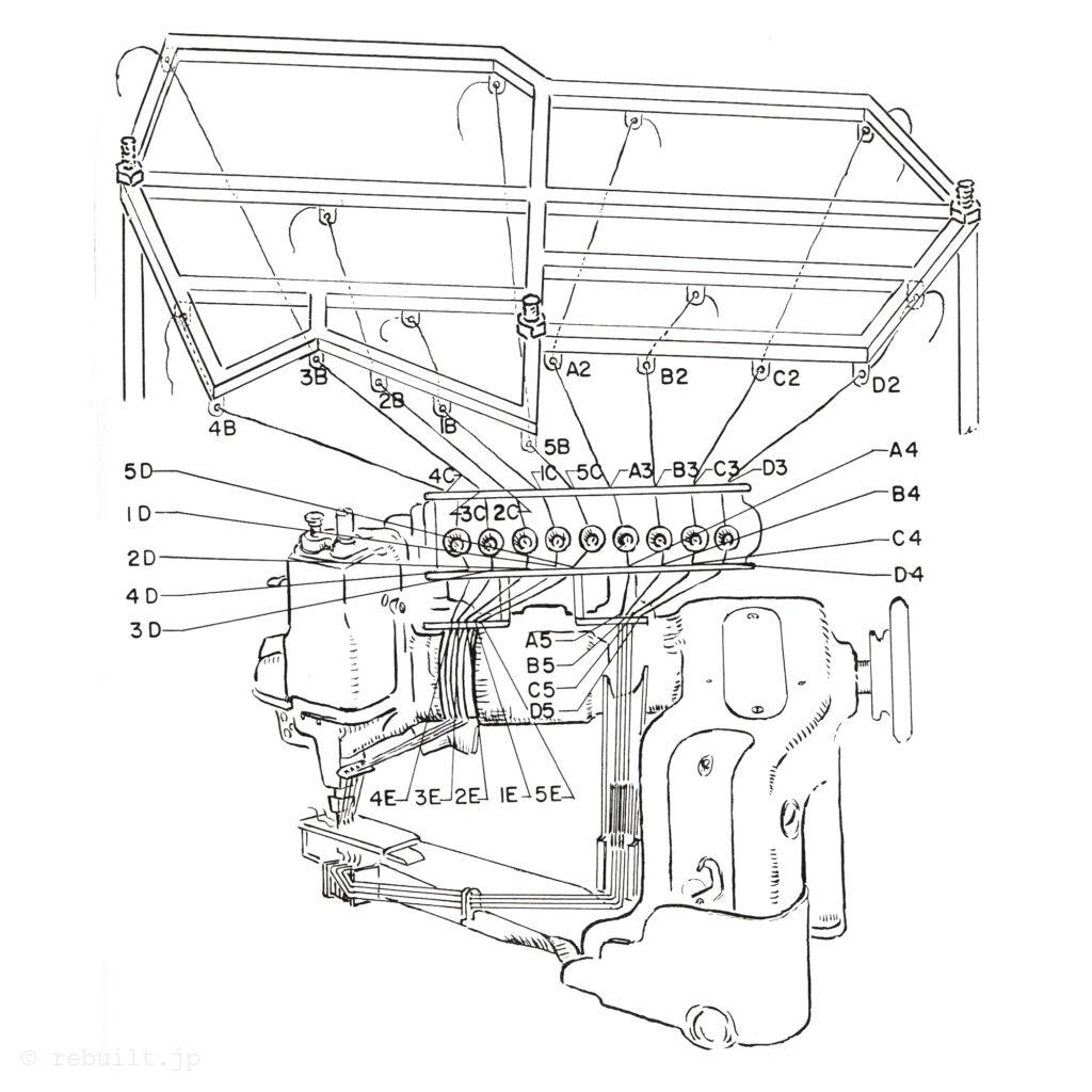
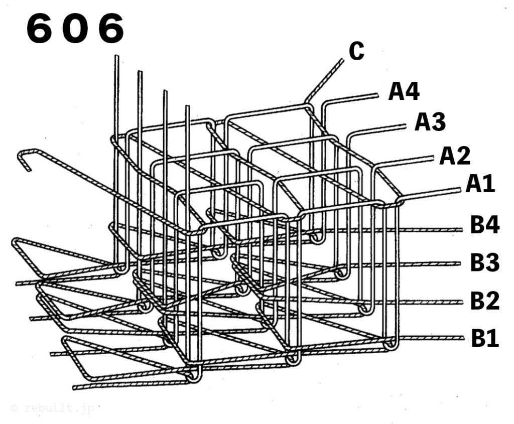
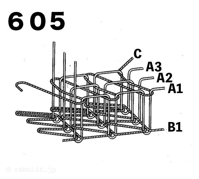
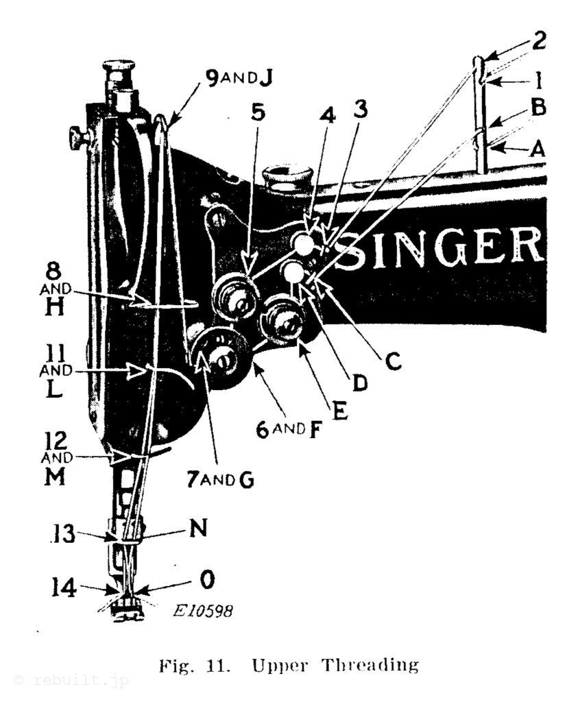
Upper Threading (See Fig. 11) To thread the right hand needle, pass the thread from the spool stand from right to left through the bottom hole (A) in the pin on top of the arm, then from back to front through the hole (B) in the pin, through the lower thread guide (C), through the lower thread retainer (D), under from right to left between the tension disks (E), under from right to left into the thread controller (F), up into the fork (G) of the thread controller against the pressure of the thread controller spring, through the thread guide (H), from right to left through the lower hole in the thread take-up lever (J), through the thread guide (1) again, and through the thread guides (L and M), through the right hand hole (N) in the needle holder and from left to right through the eye of the right hand needle (O). To thread the left hand needle, pass the thread from the spool stand from back to front through the hole (1) in the pin on top of the arm, then from right to left through the hole (2) in the pin, through the upper thread guide (3), through the upper thread retainer (4), over from right to left between the left tension dises (5), under from right to left into the thread controller (6), up into the fork (7) of the thread controller against the pressure of the thread controller spring, through the thread guide (8), from right to left through the upper hole in the thread take-up lever (9), through the thread guide (8) again, and through the thread guides (11 and 12), through the left hand hole (13) in the needle holder and from right to left through the eye of the left hand needle (14). Draw about three inches of thread through the eye of each needle with which to commence sewing.
To Prepare for Sewing With the left hand hold the ends of the needle threads, leaving them slack from the hand to the needles. Turn the balance wheel over toward you until the needles move down and up again to their highest point, thus catching the bobbin threads; draw up the needle threads and the bobbin threads will come up with them through the holes in the throat plate. Lay the threads back under the presser foot and close the hook covers.
To Commence Sewing Place the material beneath the presser foot, lower the presser foot and commence to sew.
To Remove the Work Stop the machine with the thread take-up lever at the highest point, raise the presser foot, draw the work back and cut the threads on the thread cutter which is attached to the rear end of the bed.
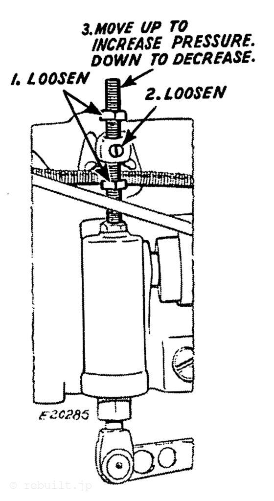
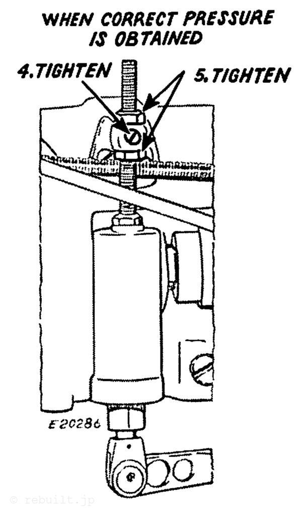
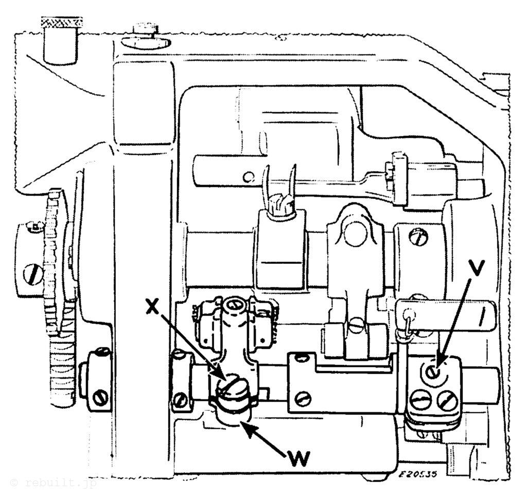
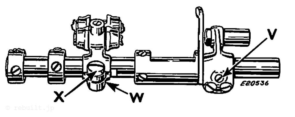
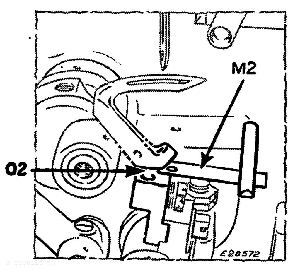
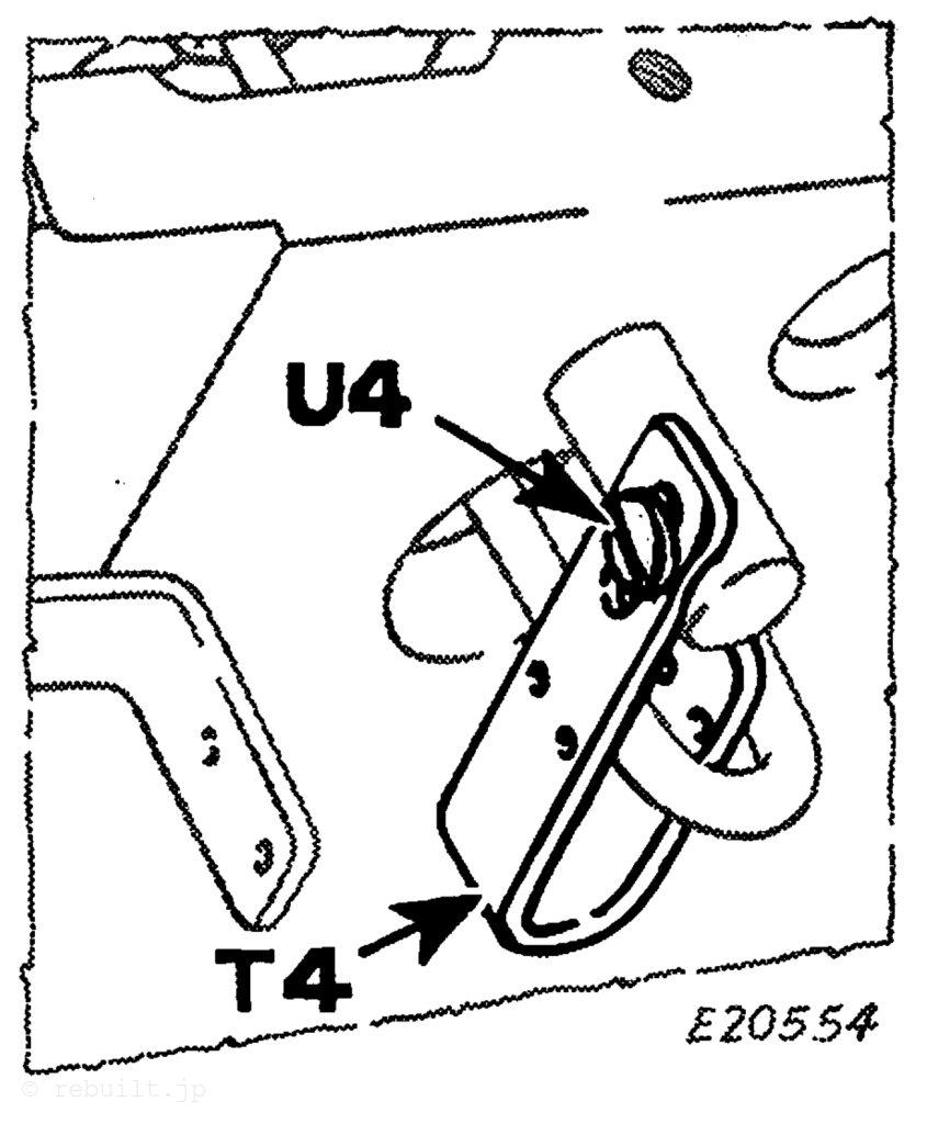
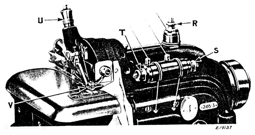
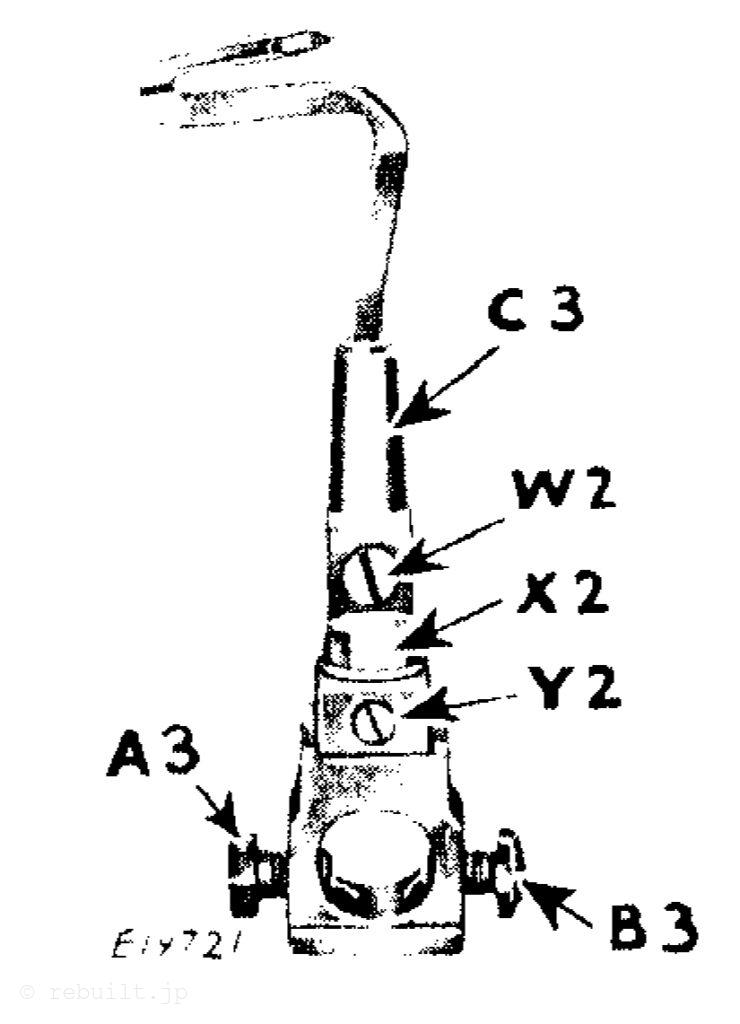
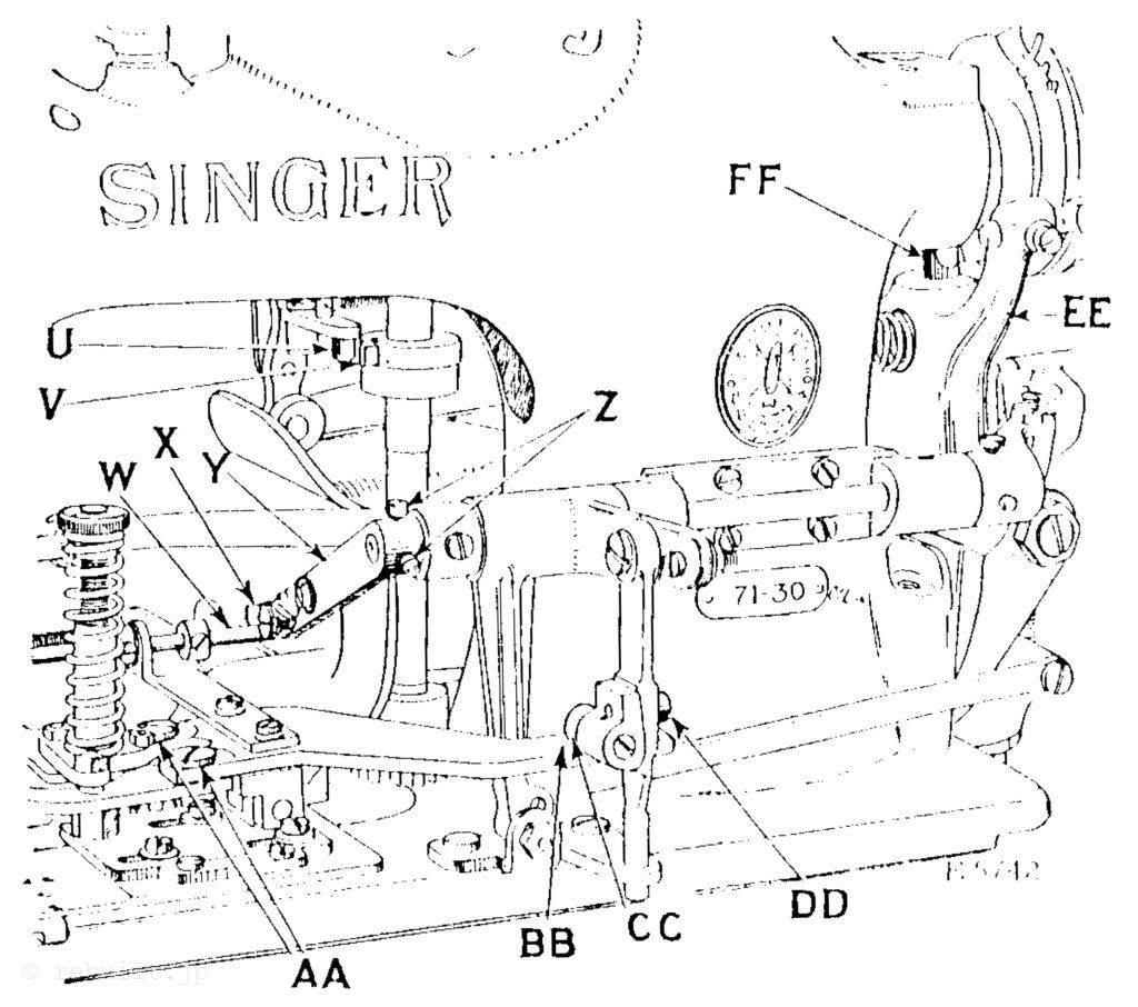
To Regulate the Pressure on the Material The pressure of the presser foot on the material should be heavy enough so that the stitches will be the same length at all speeds. The pressure on the material is regulated by the thumb screw (X, Fig. 5) at the top of the machine. To increase the pressure, loosen the set screw (W, Fig. 5) at the back of the machine and turn the thumb screw (X) downward. To decrease the pressure, turn the thumb screw (X) upward. When the required amount of pressure is obtained, tighten the set screw (W) at the back of the machine.
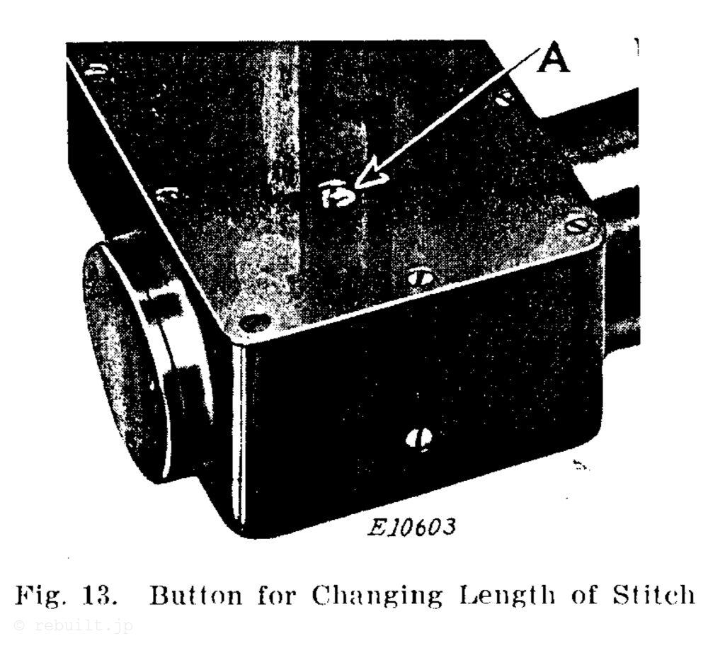
To Regulate the Length of Stitch To increase the length of stitch, press the button (A, Fig. 13) in the bed and at the same time turn the balance wheel over toward you until the desired length of stitch is obtained, then release the button (A). To shorten the stitch, turn the balance wheel over from you.
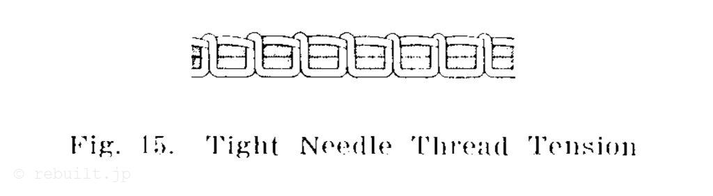
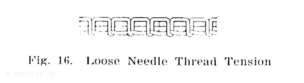
Tensions The needle and bobbin threads should be locked in the centre of the thickness of the material, thus: If the tension on the needle thread is too tight, or if that on the bobbin thread is too loose, the needle thread will lie straight along the upper surface of the material, thus: If the tension on the bobbin thread is too tight, or if that on the needle thread is too loose, the bobbin thread will lie straight along the under side of the material, thus:
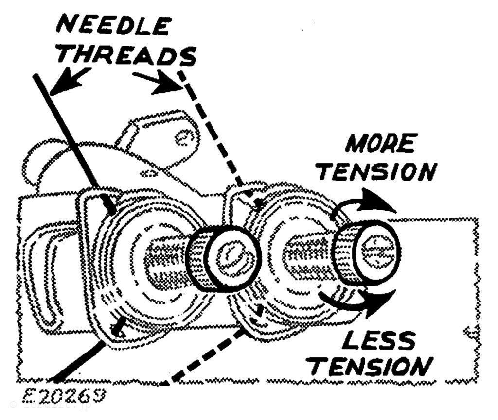
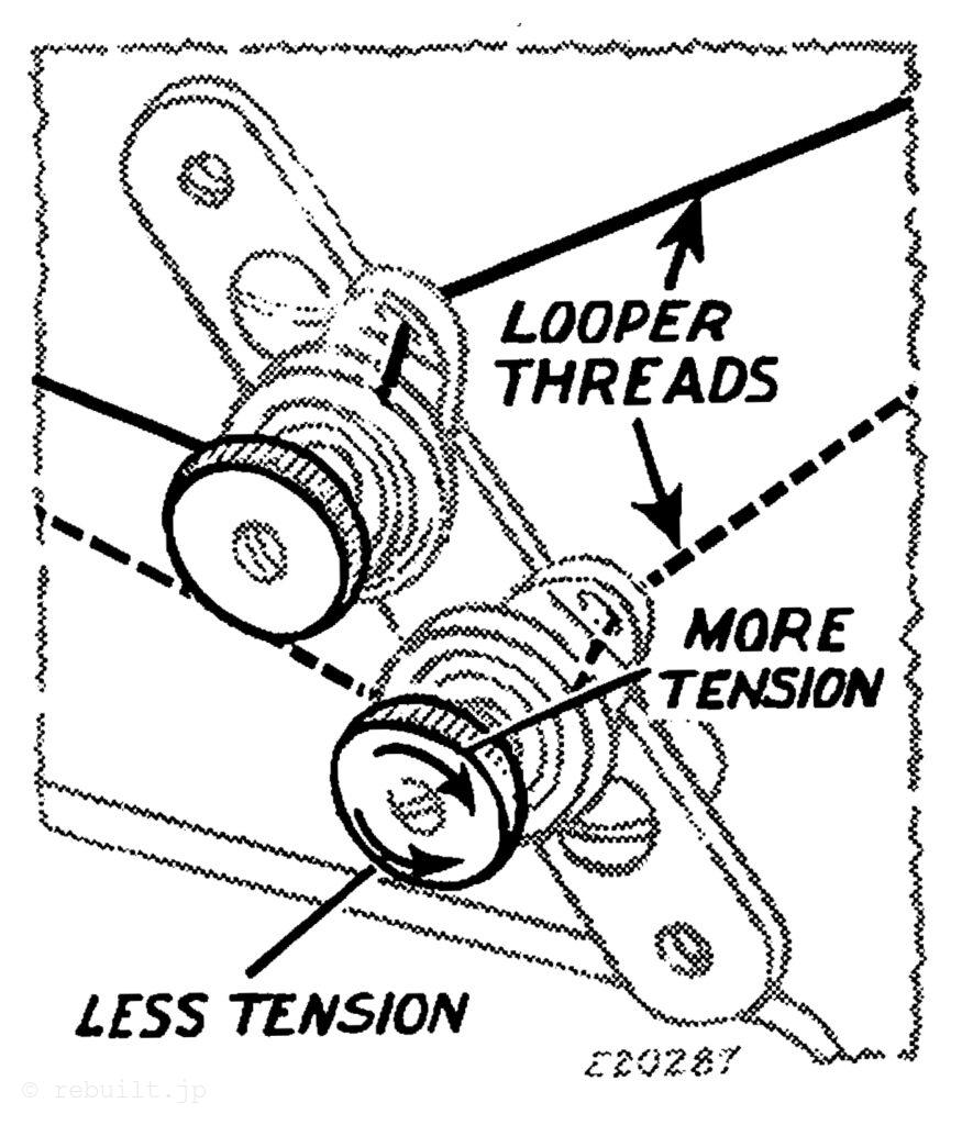
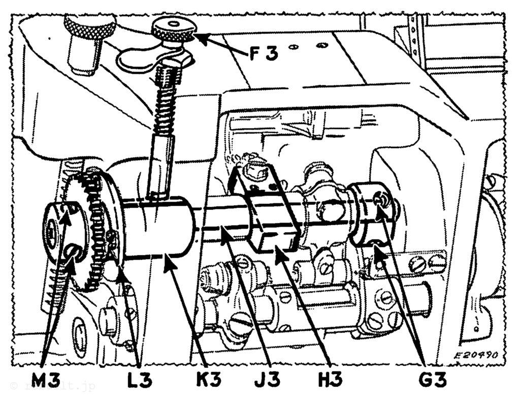
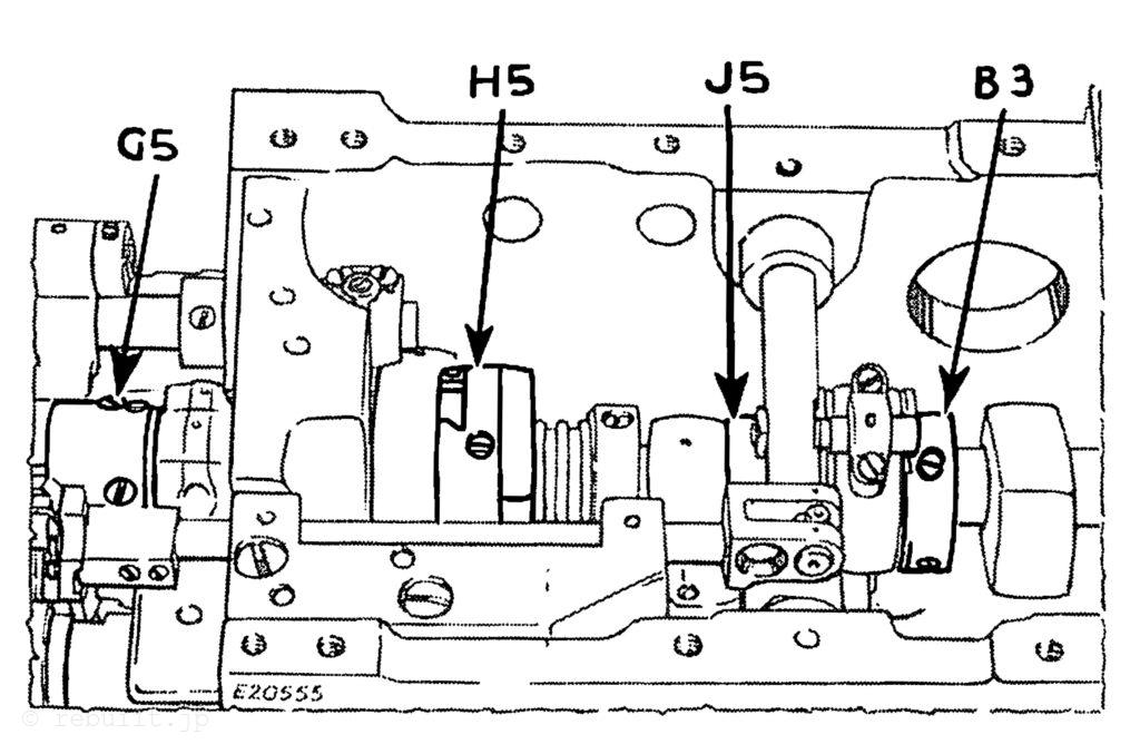
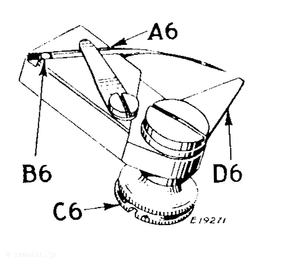
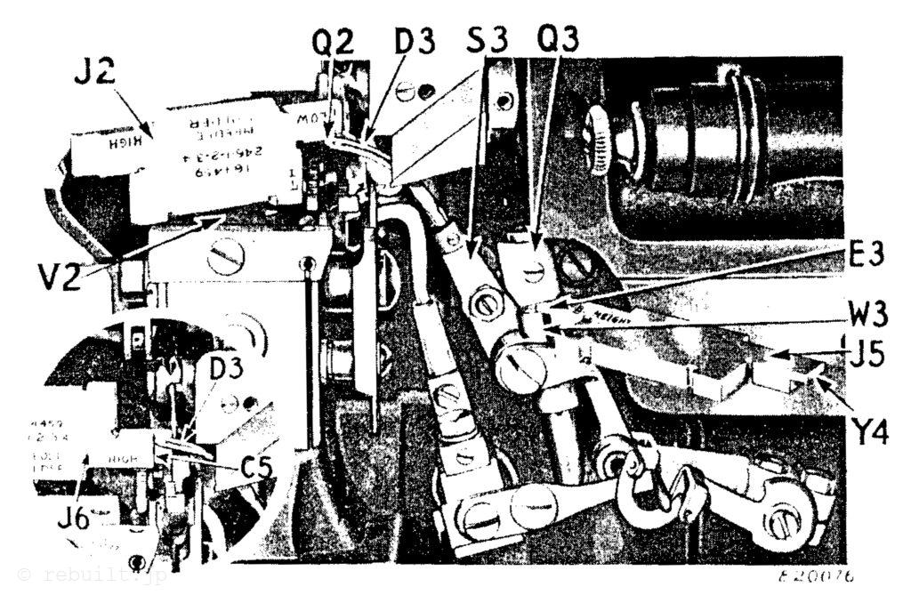
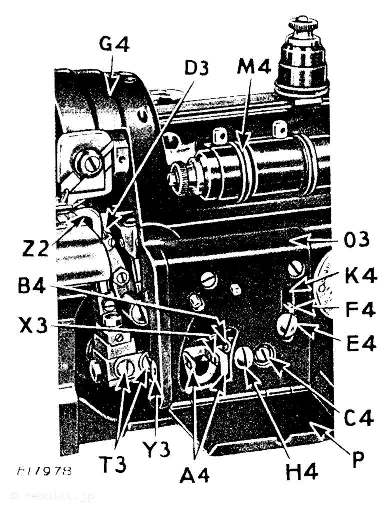
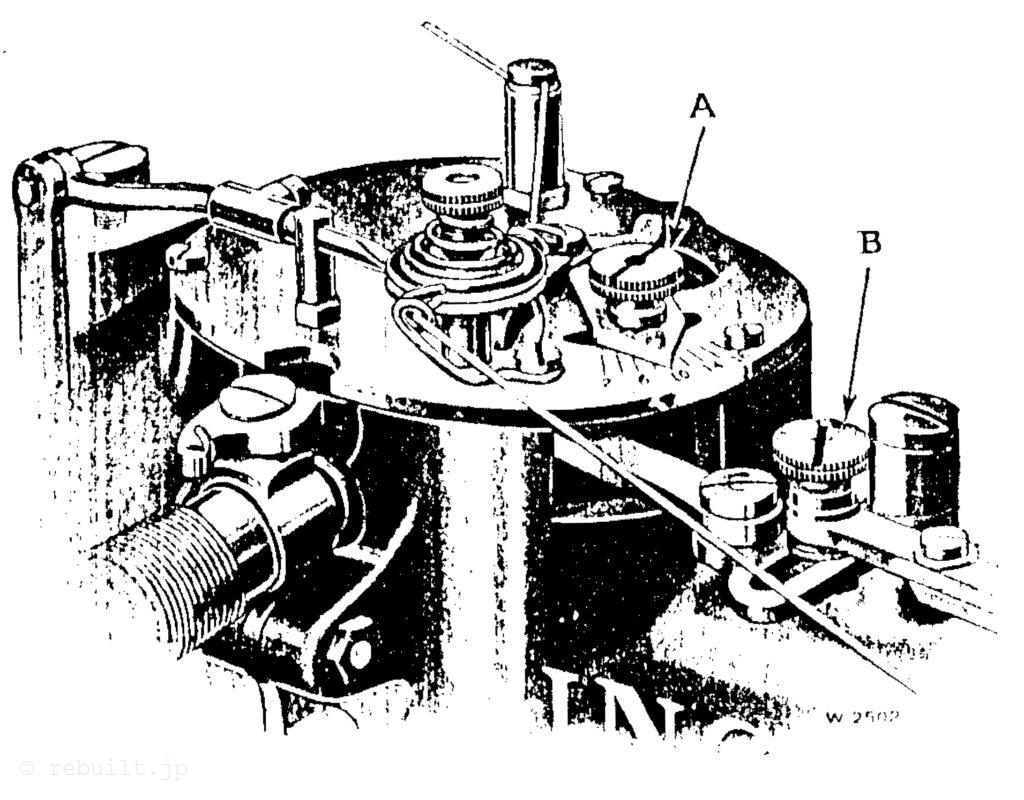
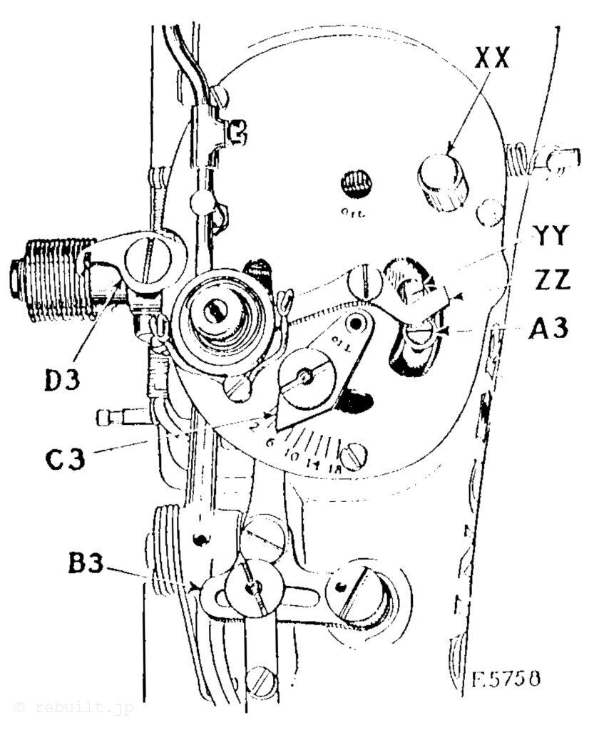
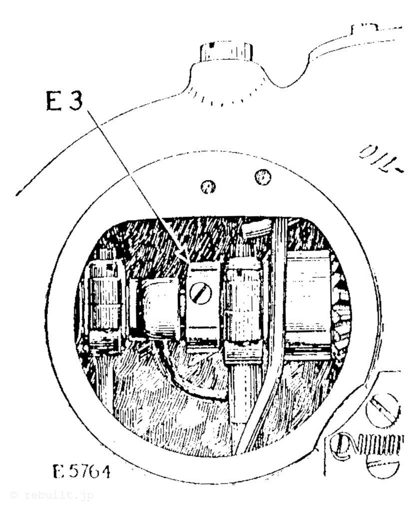
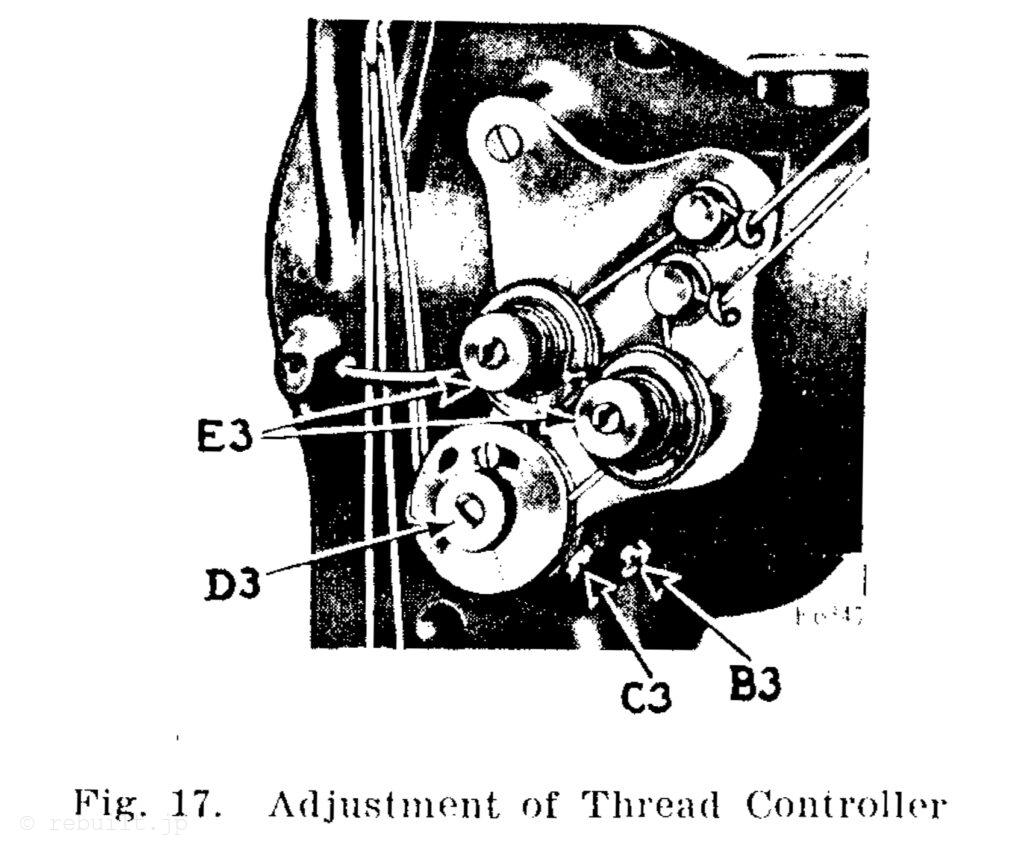
To Regulate the Tensions The tensions on the needle threads are regulated by the thumb nuts (E3, Fig. 17) at the front of the tension disks on the front of the machine. To increase the tension, turn these thumb nuts over to the right. To decrease the tension, turn these thumb nuts over to the left. The tensions on the bobbin threads are regulated by means of the screw nearest the centre of the tension spring on the outside of each bobbin case. To increase the tension, turn these screws over to the right. To decrease the tension, turn these screws over to the left.
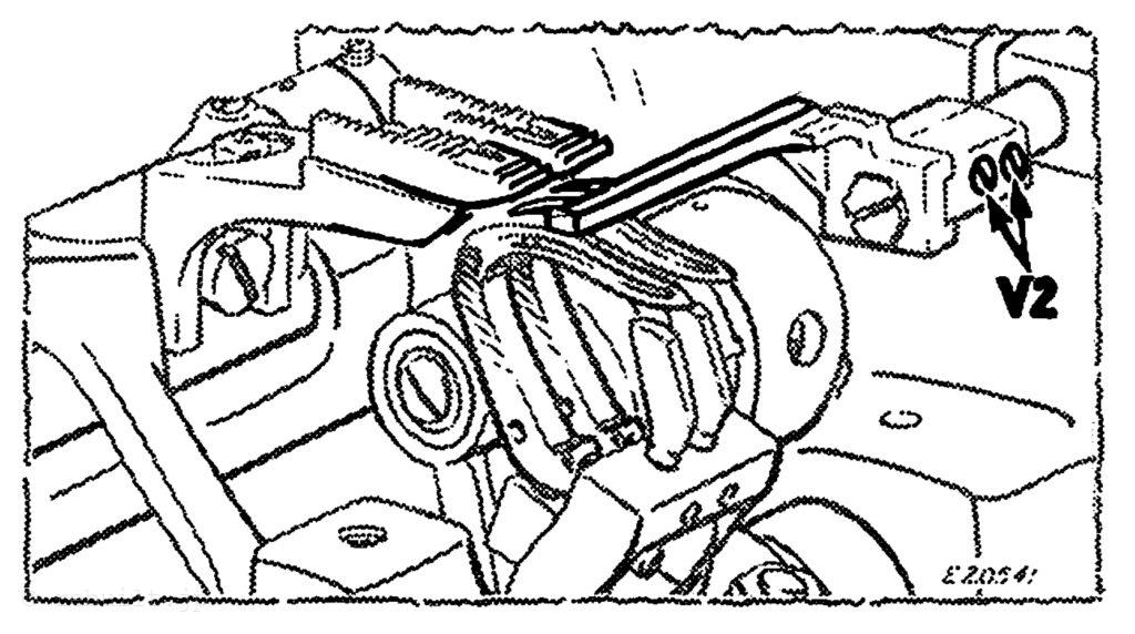
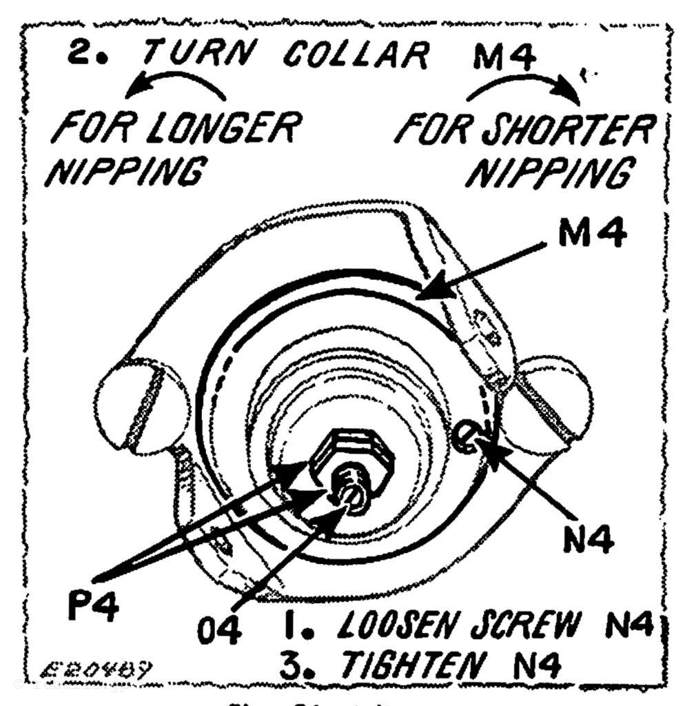
Thread Controller The function of the thread controller spring is to hold back the slack of the needle threads until the point of each needle reaches the goods in its descent, as without this controlling action of the spring, the slack thread or silk (more especially silk) will sometimes be penetrated by the point of the needle as the needle is descending. To change the thread controller stop for more controller action on the threads, loosen the set screw (C3, Fig. 17) and turn the thread controller spring stop to the right; for less action. turn the thread controller spring stop to the left, after which securely tighten the set screw (C3). It may be found advisable to increase the tension of the spring for coarse thread, or to lessen it for fine thread. To increase the tension of the thread controller on the threads, loosen the tension stud set screw (B3, Fig. 17), located nearly under the tension stud, and turn the tension stud (D3, Fig. 17) slightly to the left with a screw driver, or to decrease the tension, turn it to the right and retighten the stud set screw (B3).
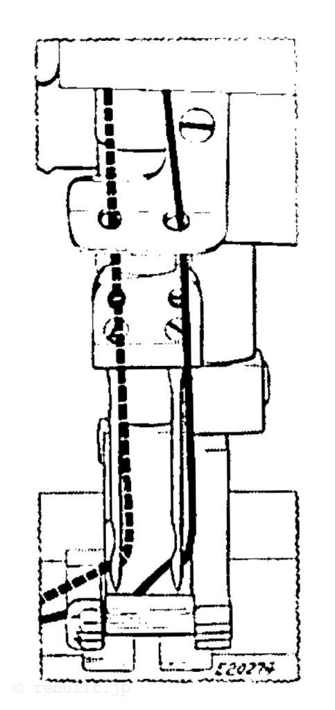
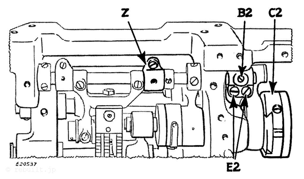
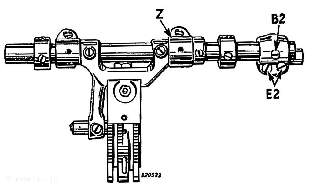
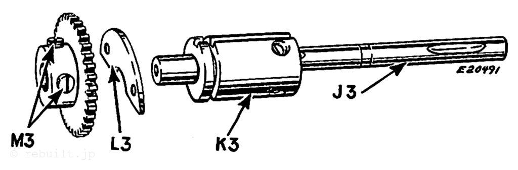
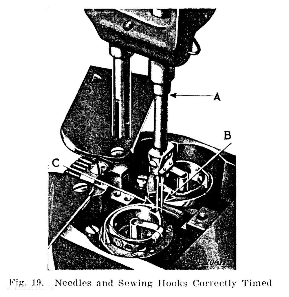
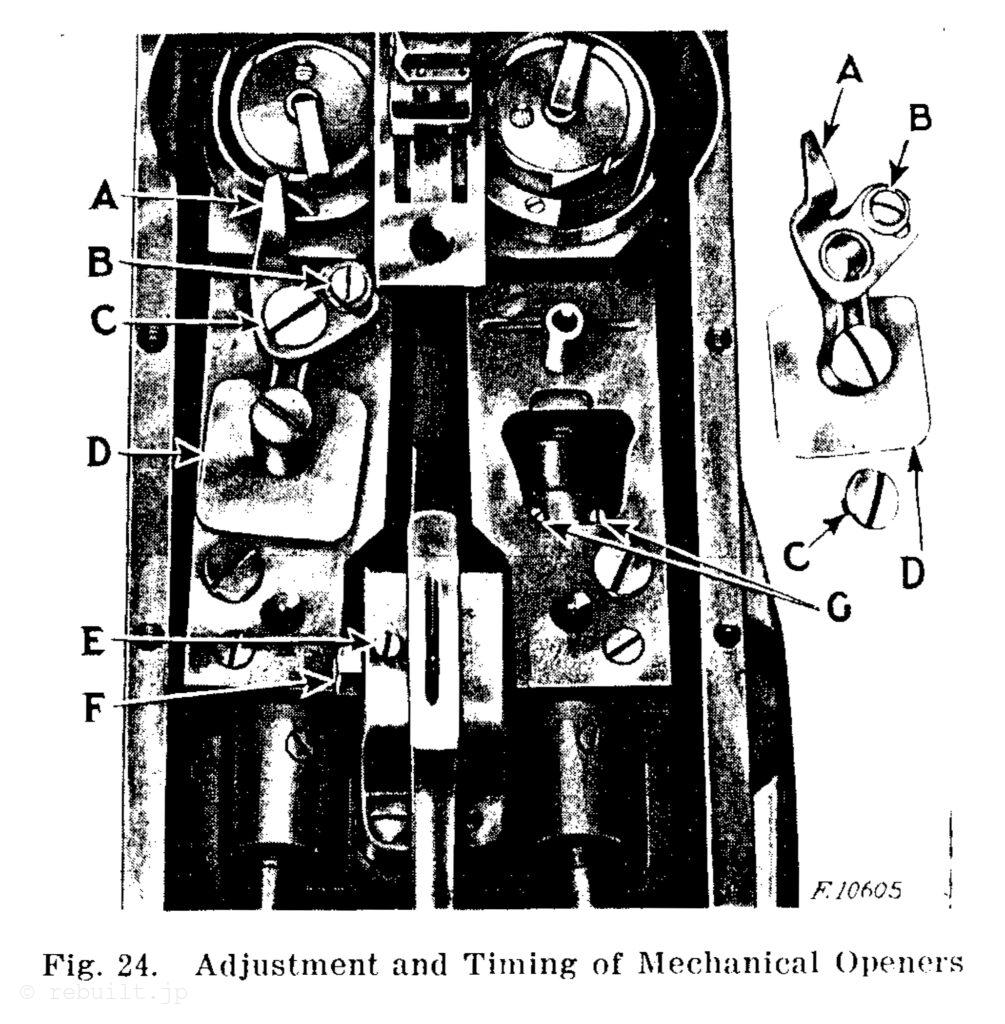
釜のタイミングを合わせるには 釜カバーを後ろに開き、押さえ金と針板を取り外します。次に、長いカバープレートをミシンベッドの上部に固定している13本のネジを外します。カバープレートを取り外す際は、ガスケットを損傷しないように注意してください。ネジ(C、図24)を外し、メカニカルオープナーレバーがストロークの中央に来るまでテンプを前後に回転させます。次に、メカニカルオープナーアセンブリ(D、図24)を持ち上げます。 (この時点でこれらのアセンブリを外すのは、針板を外した後にボビンケースが正しい位置を失うのを防ぐためです。) 新しい針が 2 本ミシンにセットされていることを確認し、テンプを手前に回して、針棒が最下点を通過して上昇し、図 19 の A に示すように、針棒の下側のタイミング マークが針棒ブッシングの下端と一直線になるようにします。針棒がこの位置にあるとき、図19 の B と C に示すように、各フックの先端が針の中心にあり、針穴から 1 インチ上にくるようにします。 上記のようにフックのタイミングが正しく調整されていない場合は、ギアの 2 本のネジ (左手フックの場合は K、右手フックの場合は D、図20) を緩めて、図 19 の B と C に示すようにフックを目的の位置に回します。次に、ギアの 2 本のネジを締めます。
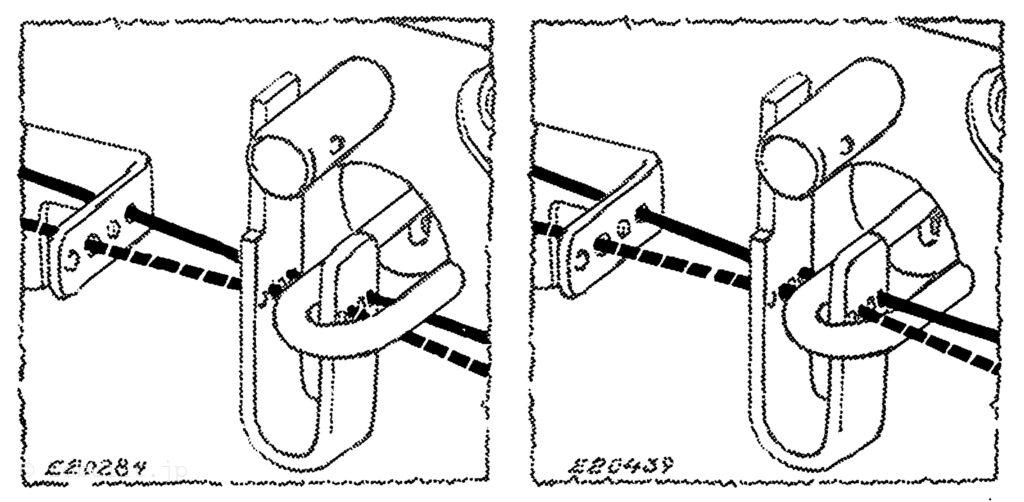
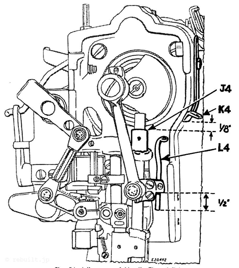
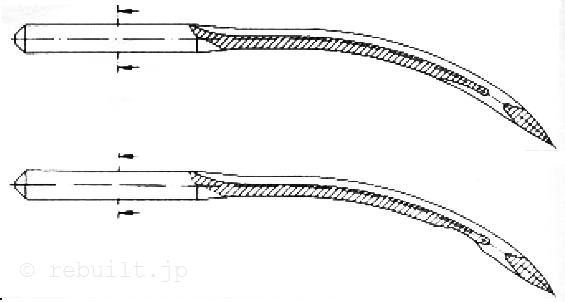
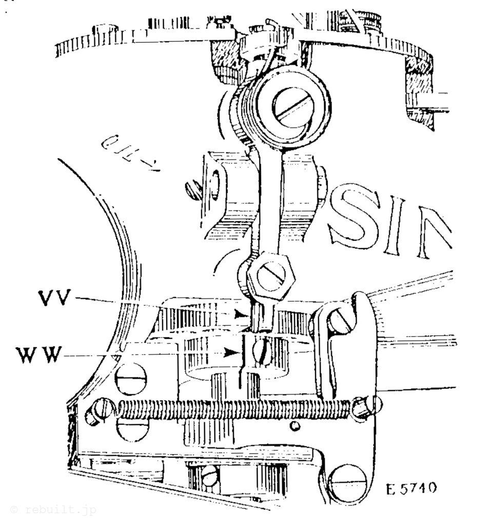
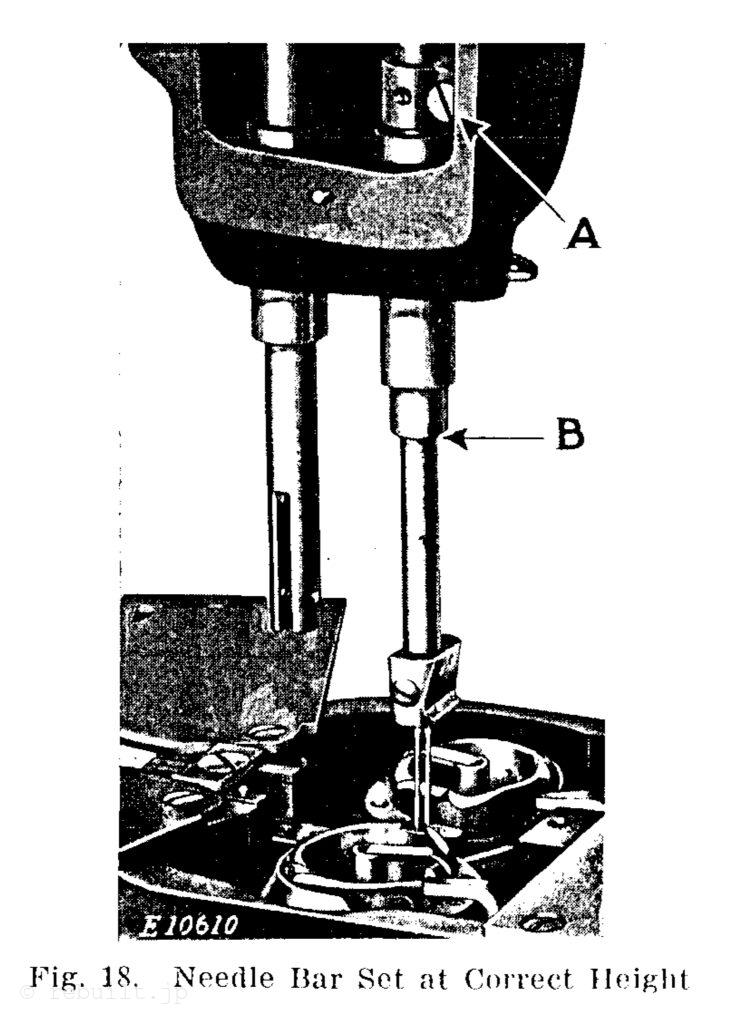
To Set the Needle Bar at the Correct Height See that the needles are pushed up into the needle holder as far as they will go. The needle bar which is in the machine when shipped from the factory, has upon it (about two inches from the bottom) two lines .080 inch apart. When the needle bar is at its lowest point, the upper timing mark on the needle bar should be in line with the lower end of the needle bar bushing, as shown at Bin Fig. 18. In case the needle bar is not set at the correct height, it can be adjusted by loosening the screw (A. Fig. 18) in the needle bar connecting stud and moving the needle bar up or down, as may be required. To Set a New Needle Bar Which Has no Mark. Set the needle bar so that when it rises .080 inch from its lowest position, the points of the sewing hooks will be at the centre of the needles and about’ inch above each eye.
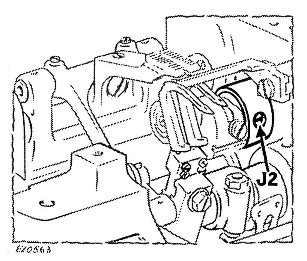
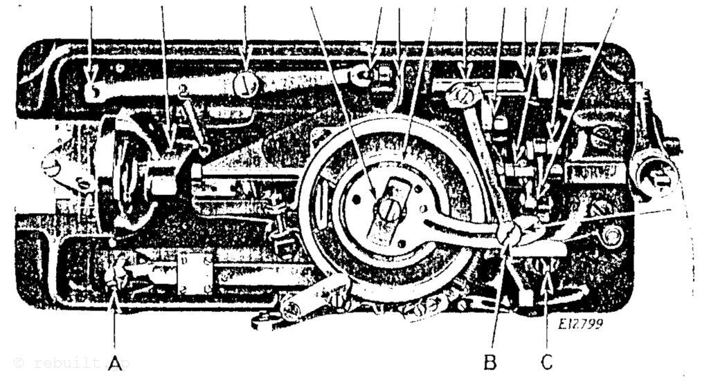
To Time the Sewing Hooks Swing back the hook covers and remove the presser foot and throat plate, then remove the 13 screws which fasten the long cover plate to the top of the bed, using care not to damage the gasket when removing the cover plate, remove the screws (C, Fig. 24) and turn the balance wheel back and forth until the mechanical opener lever is at the centre of its stroke, then lift out the mechanical opener assembly (D, Fig. 24). (These assem- blies are removed at this time to prevent damage to the bobbin cases which lose their correct position after the throat plate has been removed.) See that two new needles are set in the machine, then turn the balance wheel over toward you until the needle bar has passed its lowest point and has risen so that the lower timing mark on it is in line with the lower end of the needle bar bushing, as shown at A in Fig. 19. When the needle bar is in this position, the point of each hook should be at the centre of its needle and j’ inch above the eye, as shown at B and C, Fig. 19. In case the hooks are not correctly timed as instructed above, loosen the two screws in the gears (K, for the left hand hook, or D, for the right hand hook, Fig. 20) and turn the hooks to the desired position, as shown at B and C, Fig. 19, then tighten the two screws in the gears.
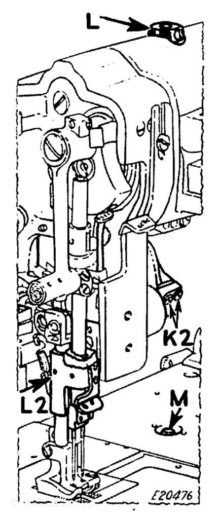
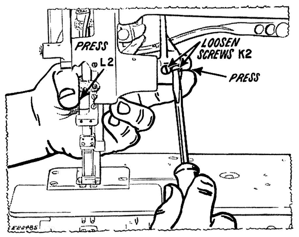
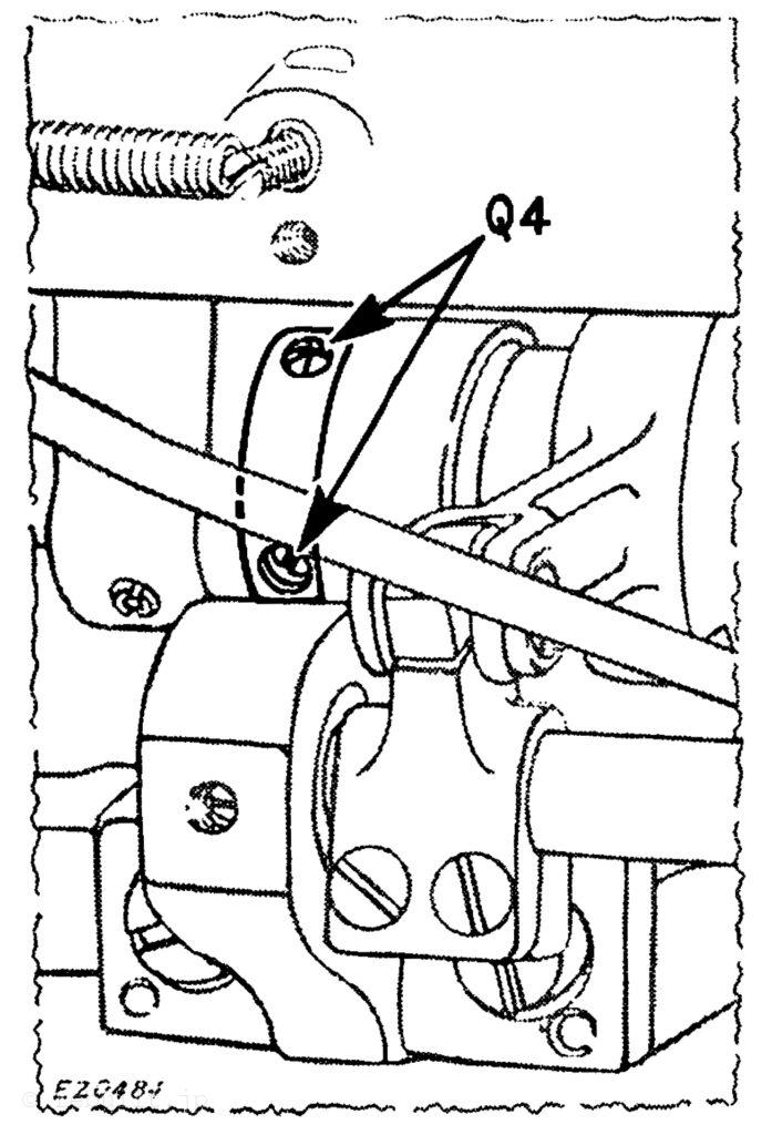
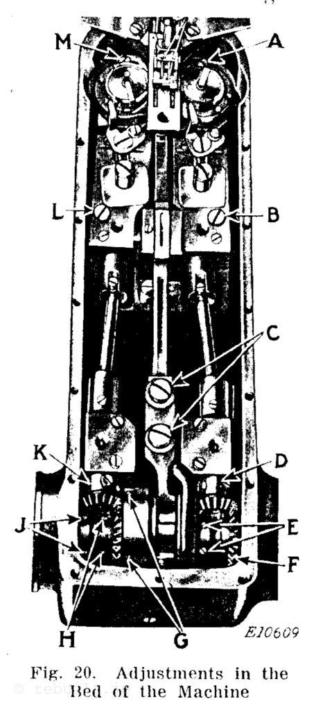
釜先を針に近づけるには、釜の先端は、針に触れずに、できるだけ針の近くを通るようにします。 左釜サドルを調整するには、バランスホイールを 手前の方向に回し、釜の先端が針の中心にくるようにします。ミシンベッドの 2 本のネジ (L と M、図 20) を緩め、必要に応じて左かぎサドルを右または左に動かし、左釜の先端が左針に接触せずに、できるだけ近くなるまで動かします。次に、2 本のネジ (L と M) をしっかりと締めます。 右釜サドルを調整するには、2 本のネジ (A と B、図 20) を緩め、必要に応じて右釜サドルを右または左に動かし、右かぎが右針に接触せずに、できるだけ近くなるまで動かします。次に、2 本のネジ (A と B) をしっかりと締めます。
To Set the Sewing Hooks Close to the Needles The point of the hooks should pass as close as possible to the needles without touching them. To adjust the left hand hook saddle, turn the balance wheel over toward Von until the points of the hooks are at the centre of the needles. Loosen the two screws (L and M, Fig. 20) in the bed of the machine and move the left hand hook saddle to the right or left, as may be required, until the point of the left hand hook is as close as possible to the left hand needle without coming into contact with it. then securely tighten the two screws (L and M). To adjust the right hand hook saddle, loosen the two screws (A and B, Fig. 20) and move the right hand hook saddle to the right or left, as may be required, until the right hand hook is as close as possible to the right hand needle without coming into contact with it, then securely tighten the two screws (A and B).
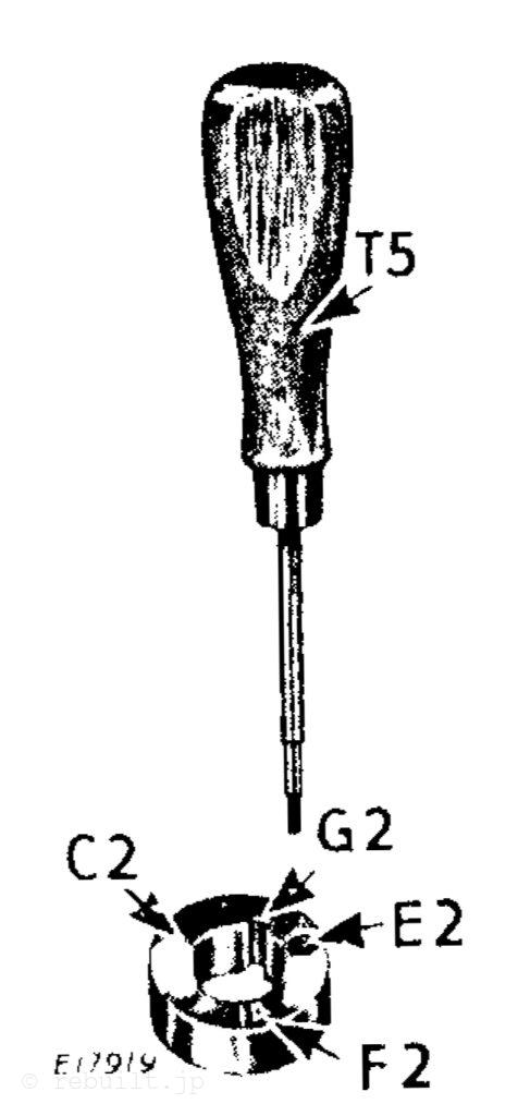
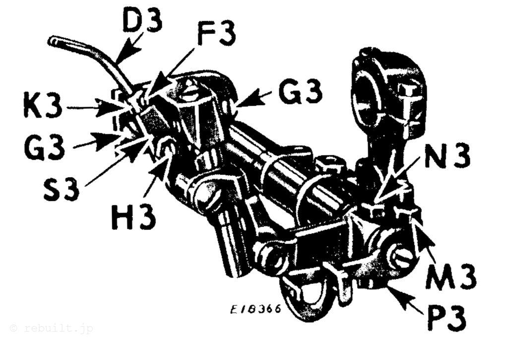
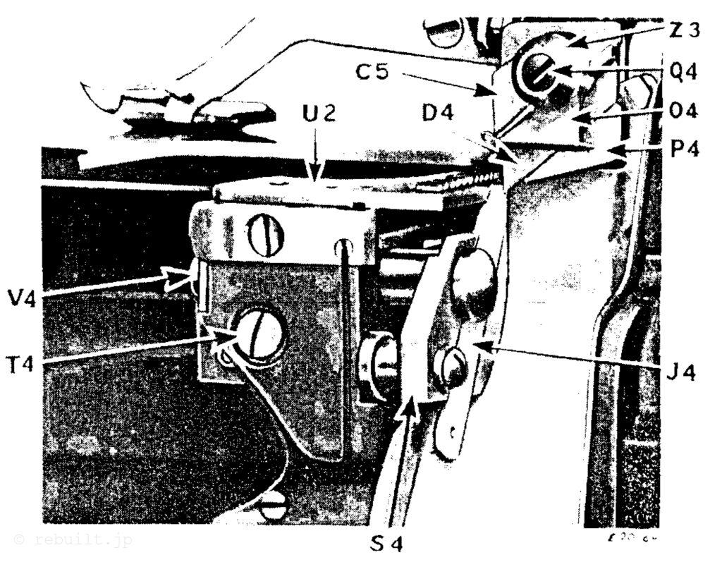
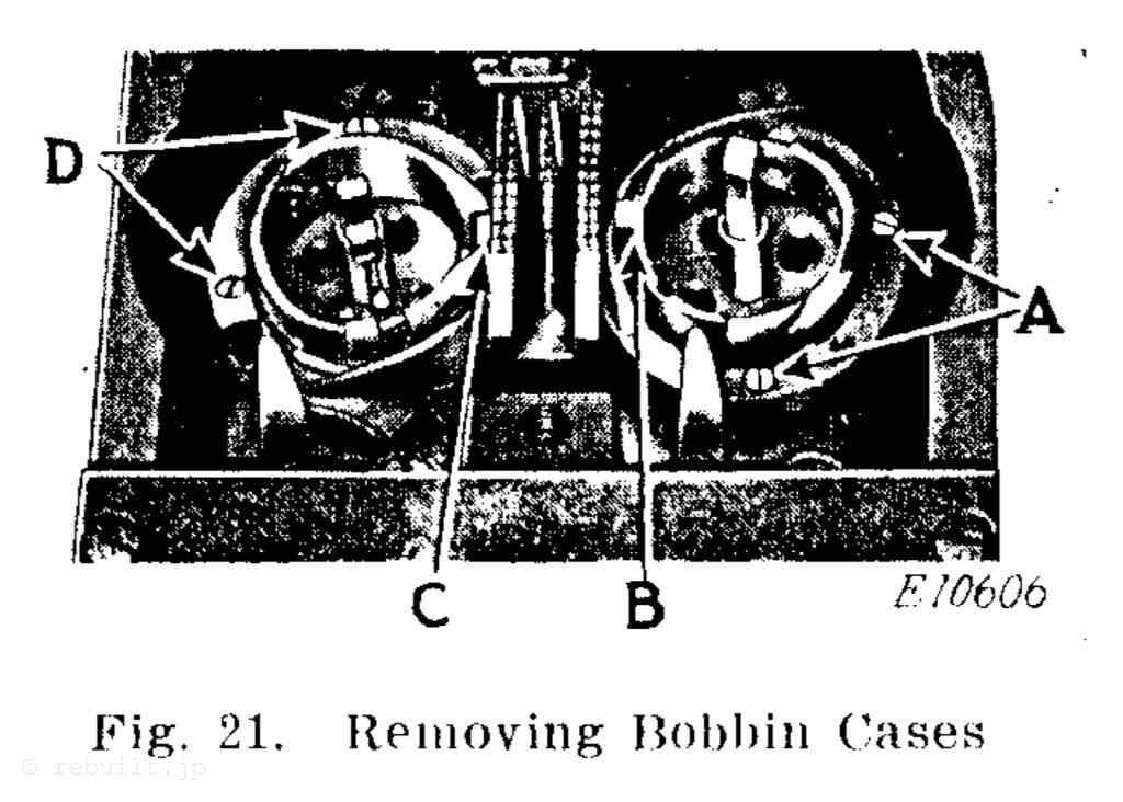
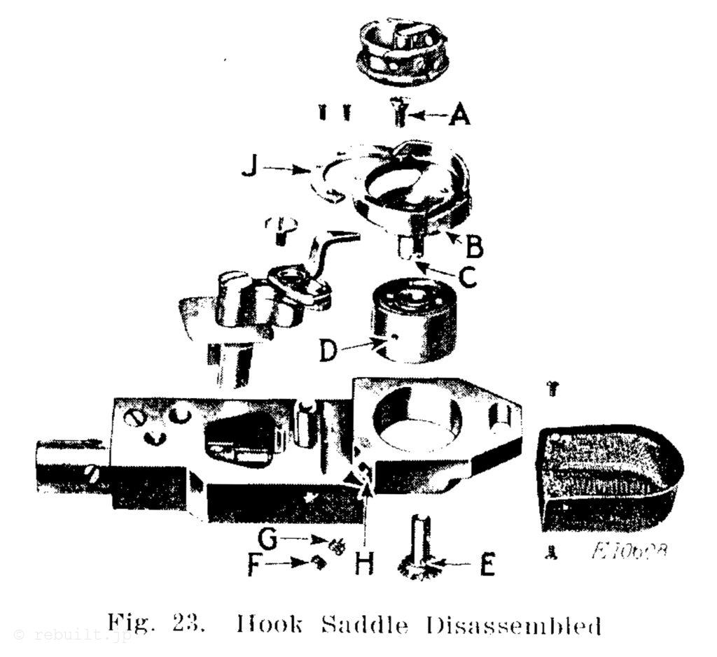
To Remove the Bobbin Cases from the Machine To remove the left hand bobbin case, remove the two hook gib screws (D), Fig. 21) from the left hand sewing hook, lift off the hook gib (J. Fig. 23) and remove the bobbin case. To remove the right hand bobbin case, remove the two hook gib screws (A, Fig. 21) and follow the above instructions.
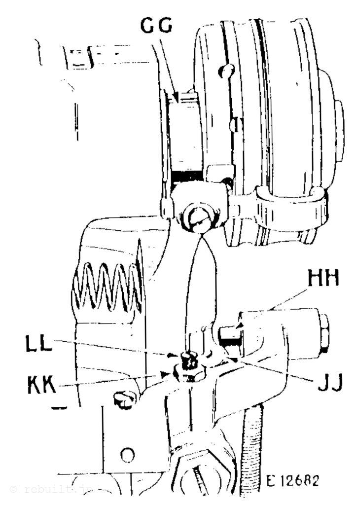
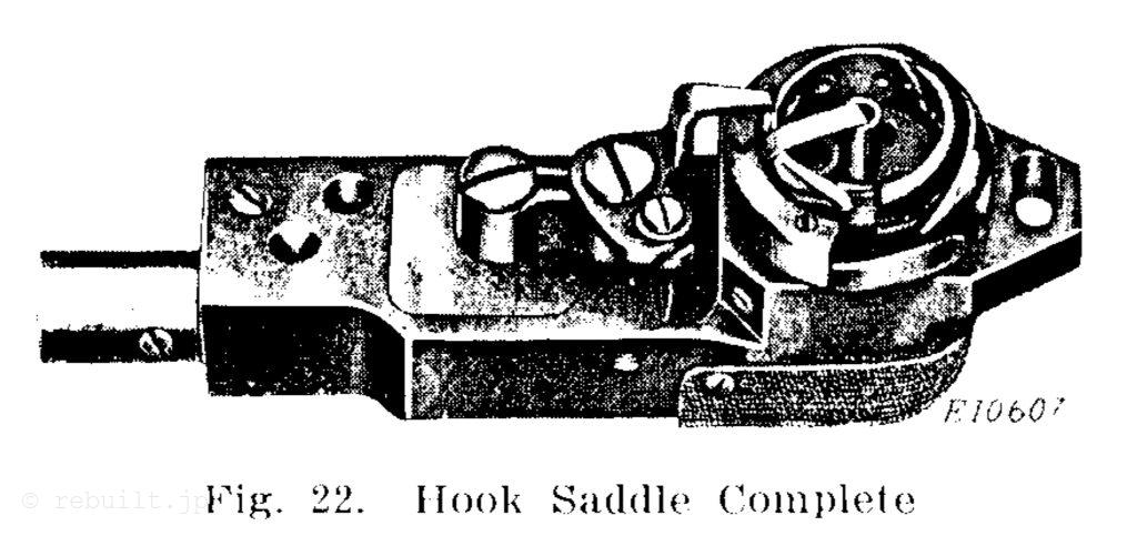
To Remove the Sewing Hooks Remove the presser foot, throat plate, feed dog and bed cover plate. Remove the screws (A, B, L and M, Fig. 20) and lift out the hook saddle, as shown in Fig. 22. Remove the mechanical opener assembly, as instructed on page 17, then remove the bobbin case, position screw (G, Fig. 23) from the screwhole (H. Fig. 23); the hook and ball bearing sleeve can then be removed from the hook saddle, as shown in Fig. 23. To remove the hook, remove the centre screw (A, Fig. 23) and withdraw the hook from the ball bearing sleeve. To replace the hook, insert the shank of the hook in the ball bearing sleeve, then replace the gear shaft in the shank of the hook, being careful to have the slot (C. Fig. 23) in the bottom of the hook shank engage the driving pin (E, Fig. 23) in the gear shaft, then replace the centre screw (A) and securely tighten it Place the hook with the ball bearing sleeve in position in the hook saddle. Care must be taken to see that the posi- tion screw (G) enters the hole shown at (D. Fig. 23) in the ball bearing sleeve, then re- place and firmly tighten the lock screw (F).
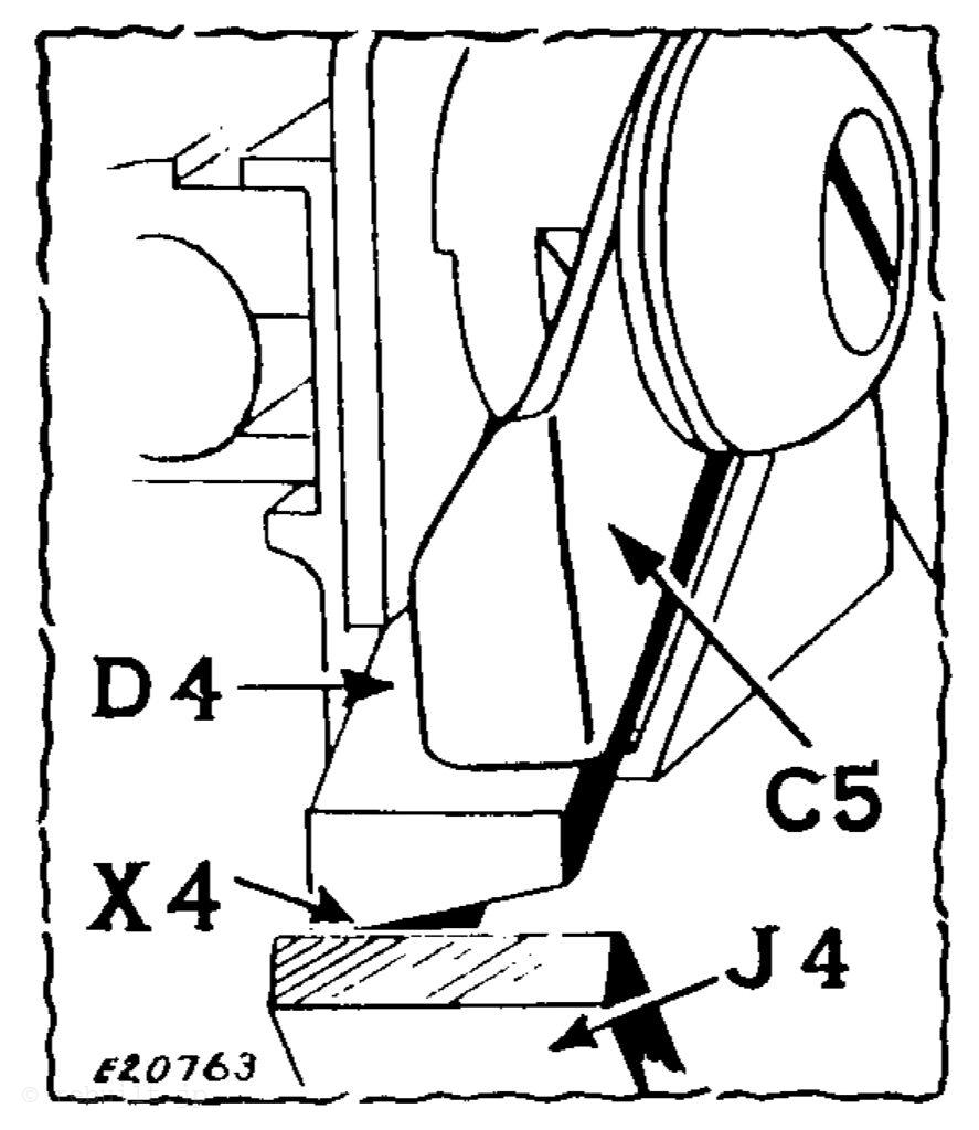
CAUTION: When replacing the throat plate, be careful to see that the notch (C, Fig. 21) in the left hand bobbin case en- gages the tongue on the left side of the throat plate, also that the lug (B, Fig. 21) on the right hand bobbin case enters the notch in the right hand side of the throat plate.
NEVER RUN THE MACHINE WITH THE THROAT PLATE REMOVED UN- LESS THE MECHANICAL OPENER LEVERS (A, Fig. 24) ARE REMOVED.
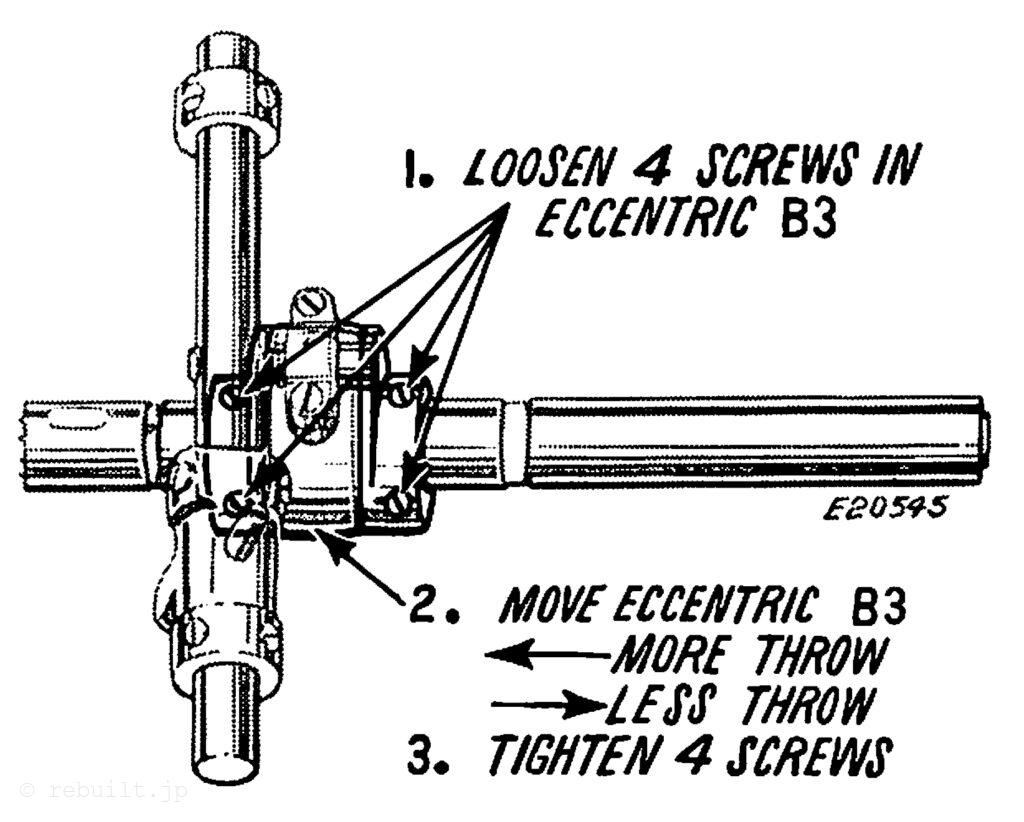
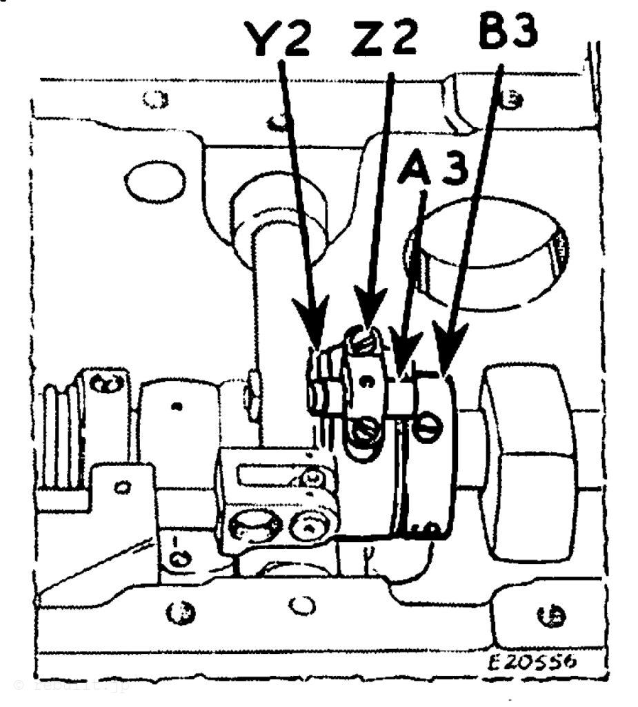
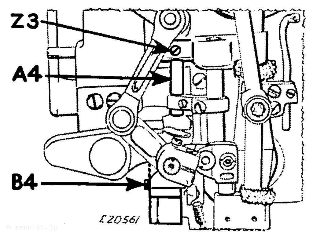
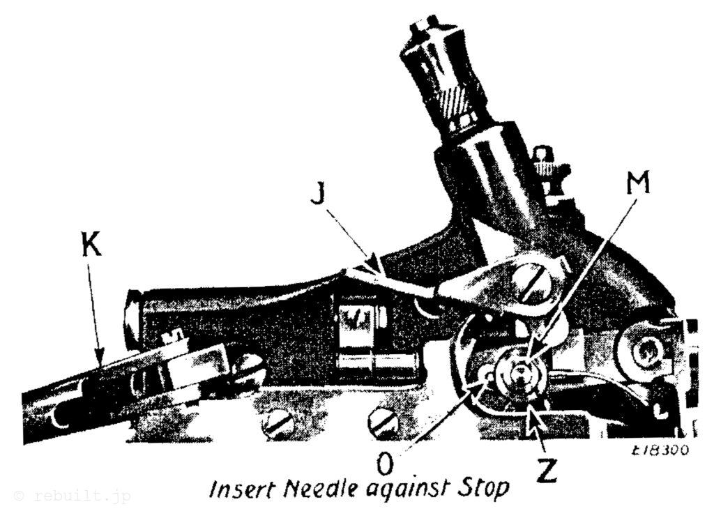
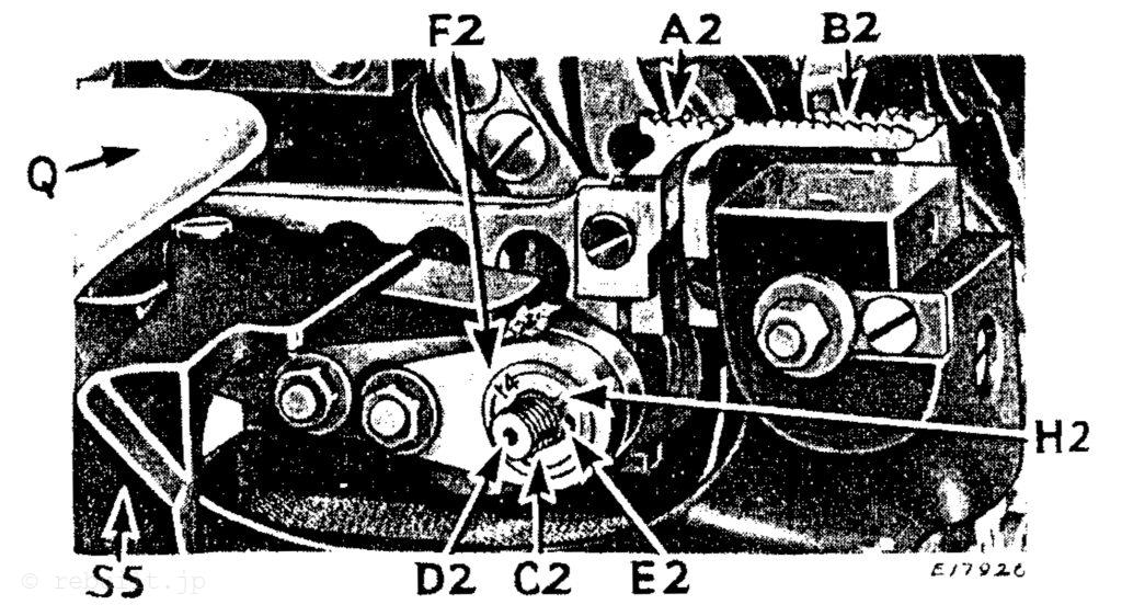
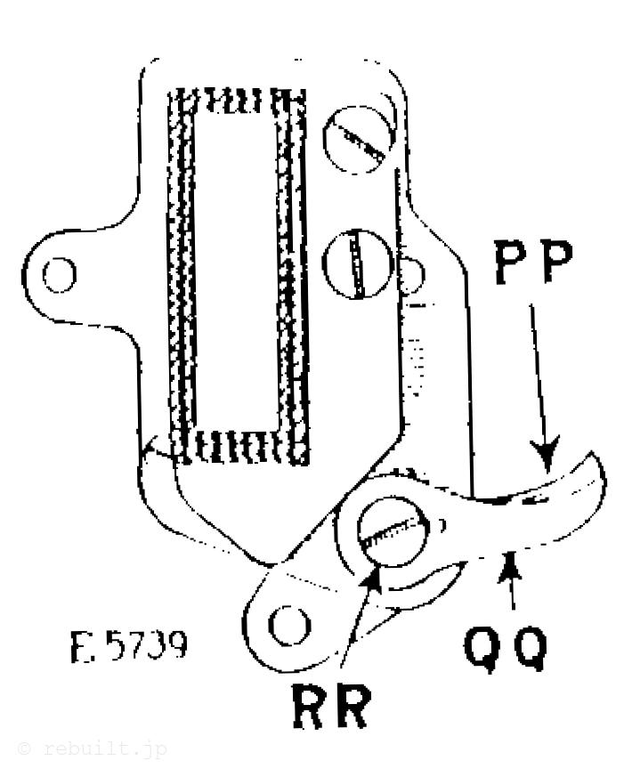
To Time and Adjust the Mechanical Openers The mechanical opener lever (A, Fig. 24) should be set so that it touches the bobbin case as lightly as possible, yet turns the bobbin case enough to make a sufficient opening for the free passage of the thread between the throat plate and the bobbin case. The mechanical opener lever (A) can be adjusted by loosen- ing the screw (B, Fig. 24) and moving the lever (A), as required. The screw (B) can be reached without removing the bed cover plate. These instructions apply to both opener levers. To change the timing of the mechanical openers, remove the screw (C, Fig. 24) and lift out the mechanical opener assembly (D), Fig. 24). Then loosen the two screws (G, Fig. 24) in the mechanical opener eccentric and adjust the eccentric as follows: For the right hand opener, turn the eccentric for this opener so that the opener lever will be at its extreme left hand position when the point of the right hand hook is opposite the right hand needle. For the left hand opener, turn the eccentric for this opener so that the opener lever will be at its extreme left hand position when the thread take-up lever is at its highest point.
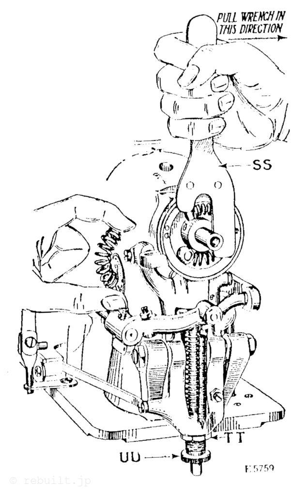
To Raise or Lower the Feed Dog The feed dog is usually set so that a full tooth appears above the upper surface of the throat plate when the feed dog is at its highest point. To make this adjustment, remove the bed cover plate, then loosen the set screw (E, Fig. 24) and using the small wrench furnished with the machine, turn the eccentric stud (F. Fig. 24) until the feed dog reaches the desired height, then tighten the set screw (E).
To Change the Position of the Feed Dog Remove the throat plate and bed cover plate, then loosen the two screws (C, Fig. 20) and move the feed dog forward or back- ward to the desired position, after which securely tighten the two screws (C).
To Time the Feeding Mechanism The rise and fall of the feed dog should be timed so that the top of the teeth of the feed dog is flush with the top surface of the throat plate when the points of the needles reach the goods. To time the rise and fall of the feed dog, loosen the two set screws (E, Fig. 20) in the feed lifting eccentric and turn the eccentric to the desired position, then tighten the two set screws (E). The forward and backward movement of the feed dog should be timed so that the feed dog starts its feeding movement when the top of its teeth are flush with the top surface of the throat plate. To time the forward and backward stroke of the feed dog, loosen the two set screws (H, Fig. 20) in the feed driving eccentric and turn the eccentric as required, then tighten the two set screws (H). Care must be taken to keep the gear which is mounted on the feed driving eccentric in correct mesh with the gear it drives. When the above adjustment is made it will be necessary to retime the left hand sewing hook, as instructed on page 17.
To Adjust the Stitch Regulator If it is necessary to disassemble the stitch regulator, when it is reassembled the friction may be increased or decreased by adjusting the two screws which are held in position by the two set screws (G, Fig. 20).
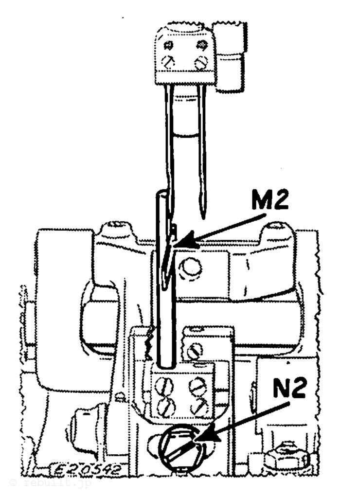
Needle Guard The function of the needle guard (B, Fig. 23) is to prevent the needles from touching the hooks, in case the needles are deflected toward the hooks. The needle guard (B), which is attached to the bottom of each sewing hook, should be bent until it prevents the needles from touching the hooks; it should not, however, be bent outwardly enough to deflect the needles from their normal path.
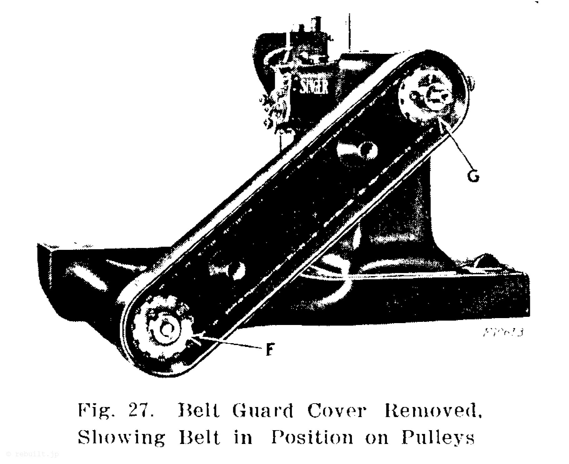
ベッドシャフトの取り外し Arm Shaft Connection Beltの指示に従って、テンプ、ベルトガードカバー、ベルトを取り外します。ベッドシャフトから下部プーリー(F、図27)を取り外し、次にアームシャフトから上部プーリー(G、図27)を取り外します。ベルトガードを固定している2つの止めネジを緩めてベルトガードを取り外し、ベッドカバープレートも取り外します。ボールベアリングカラーの2つのセットスクリュー(J、図20)を緩め、ギアの2つのセットスクリュー(II、図20)を緩め、送り上げ偏心輪の2つのセットスクリュー(E、図20)を緩め、ブッシングセットスクリュー(F、図2)を緩めます。これで、ギア(F、図20)とボールベアリングハウジング付きボールベアリングを含むベッドシャフトをミシンから引き抜くことができます。
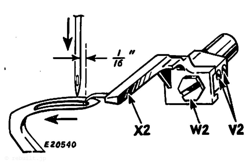
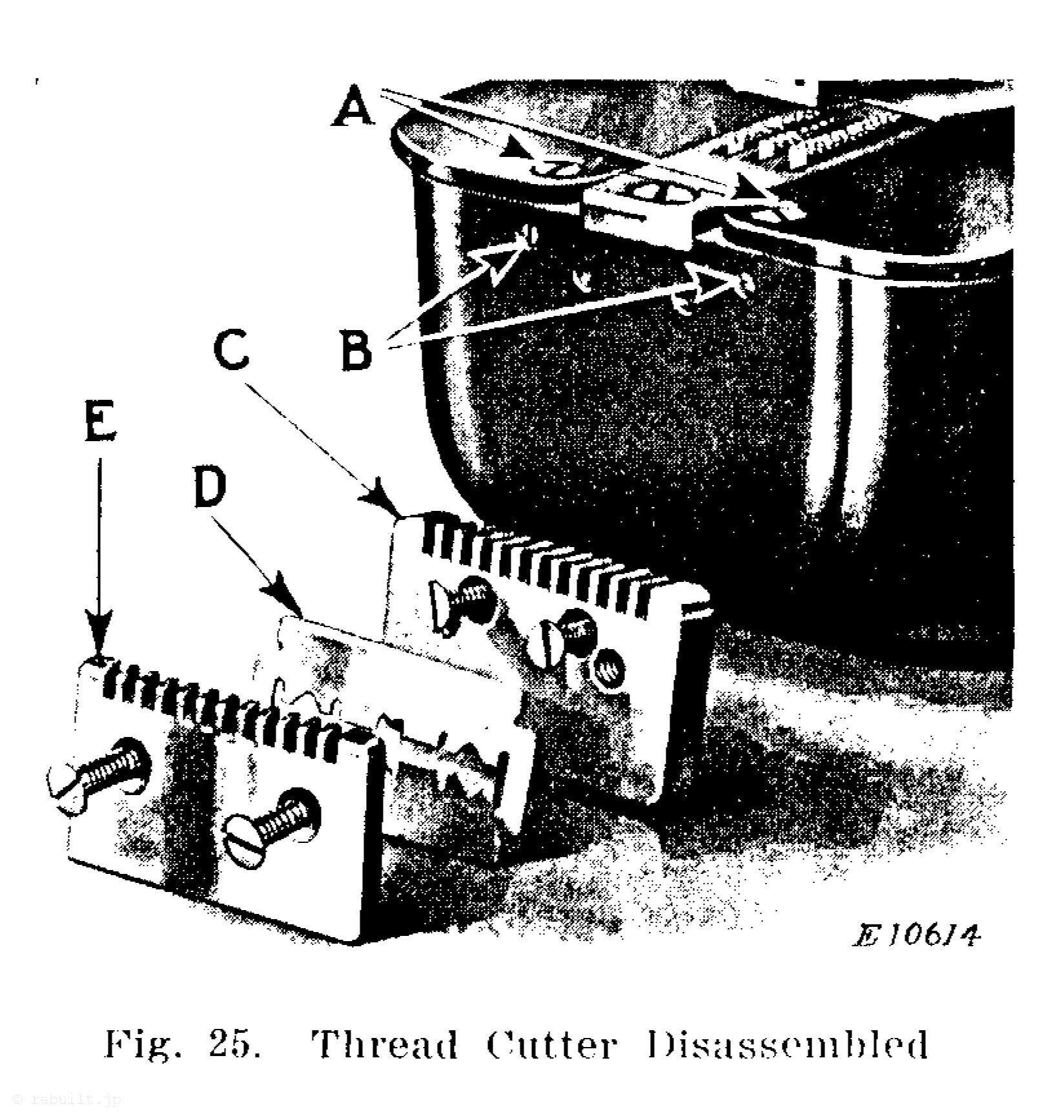
Thread Cutter Should the thread cutter blade (D, Fig. 25) become dull, re move the two screws in the clamp plate (E, Fig. 25) and turn the blade so that the other edge can be used.
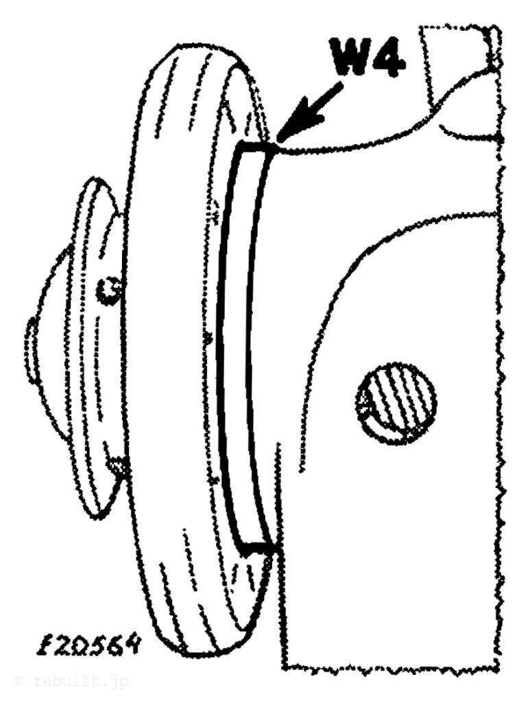
To Adjust the Hook Cover Plates If the hook cover plates open too freely, remove the two screws in the thread cutter clamp plate (E, Fig. 25), then remove the two screws which hold the thread cutter block (C, Fig. 25) to the bed of the machine. Loosen the two set screws (B, Fig. 25) and turn the screws (A, Fig. 25) to increase or decrease the friction on the hook cover plates. When the desired friction is obtained, tighten the set screws (B).
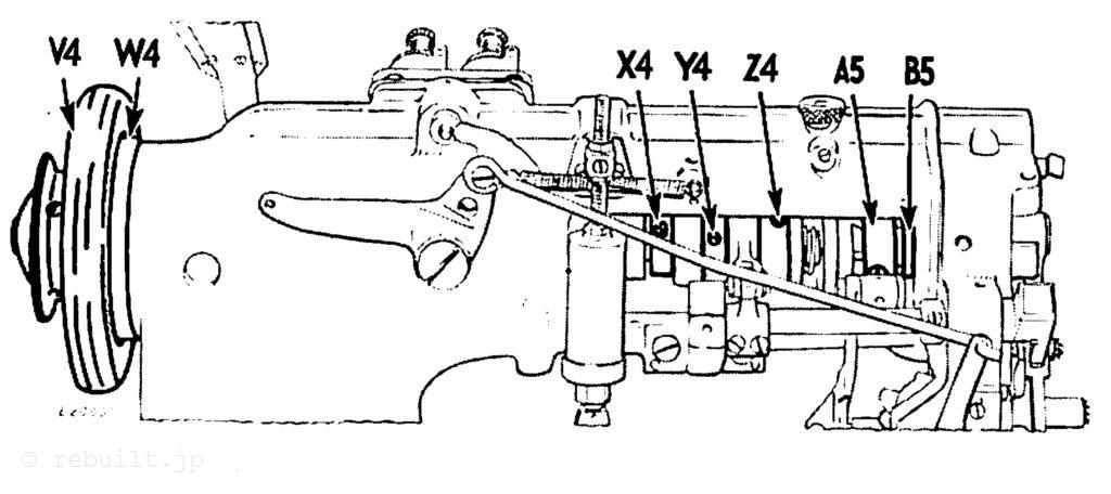
To Adjust the Needle Bar Support The needle bar support (N. Fig. 5) should be set so that it enters the hollow needle bar about ‘ inch when the needle bar is at its lowest point. To make this adjustment, loosen the set screw (0, Fig. 5) and raise or lower the needle bar support until it is set as instructed above, then tighten the set screw (0).
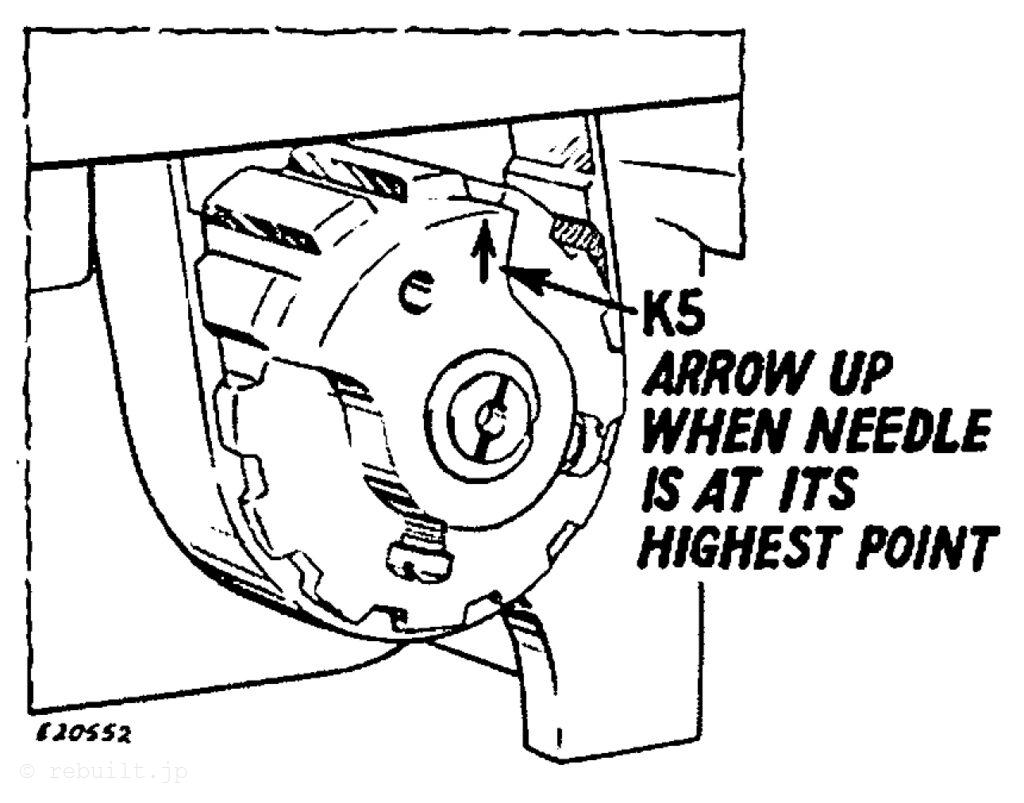
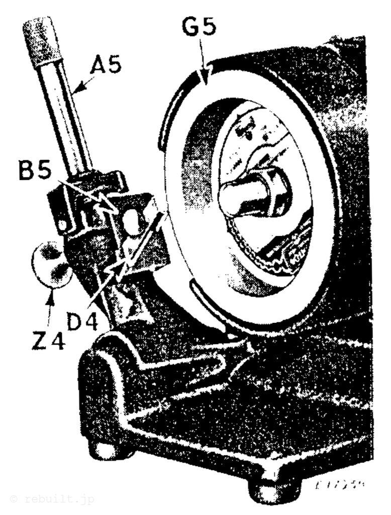
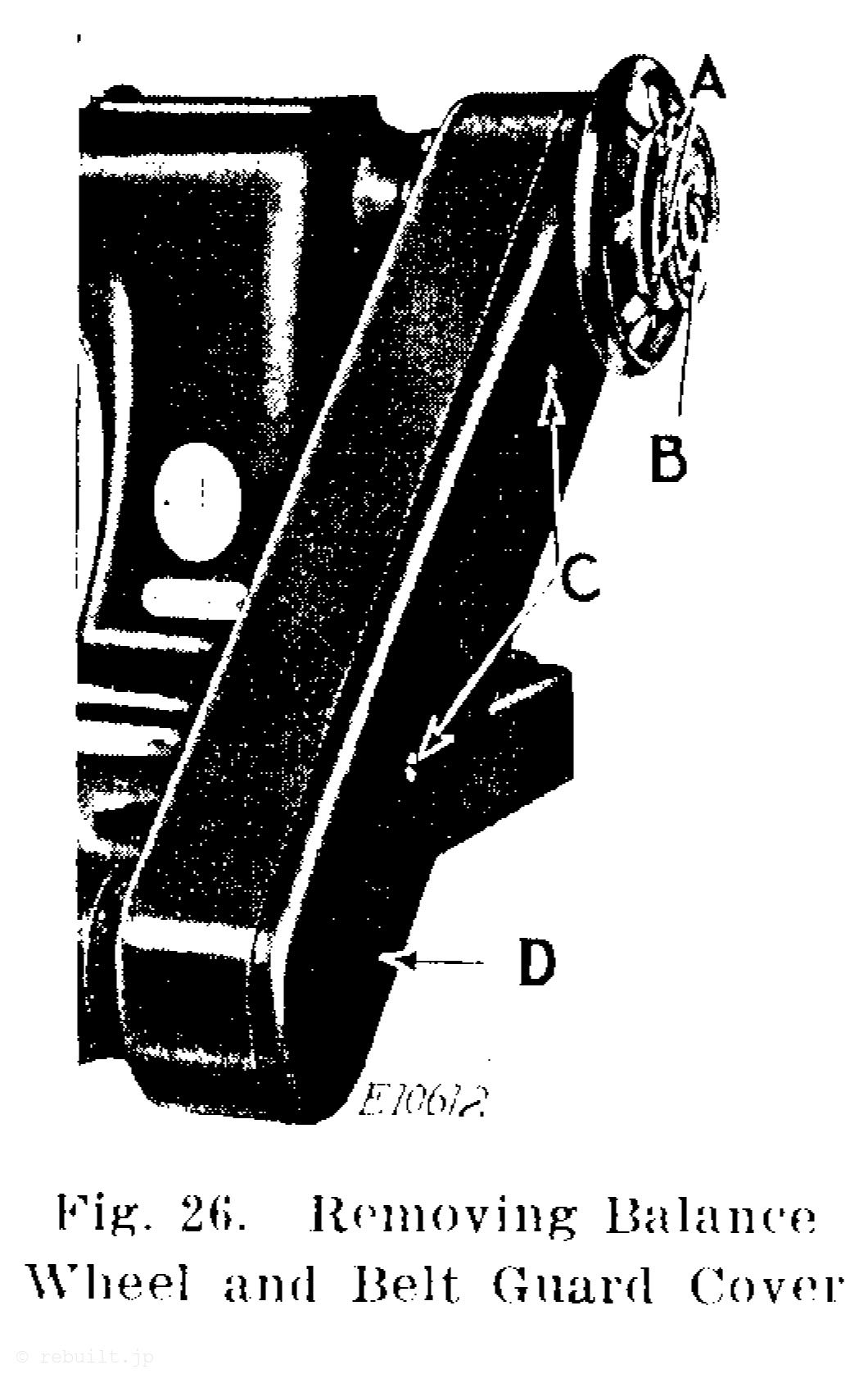
To Remove and Replace the Arm Shaft Connection Belt Remove the large screw (B, Fig. 26), loosen the balance wheel set screws (A. Fig. 26) and remove the balance wheel from the machine. Remove the two screws (C, Fig. 26) and remove the belt guard cover (D. Fig. 26). When replacing the belt, first place it over the upper pulley (G, Fig. 27), then turn the arm shaft until the needle bar is at its highest point. Now turn the lower pulley (F, Fig. 26) until the feed dog is at its highest point, keeping the pulleys in time with each other, and place the belt on the lower pulley (F).
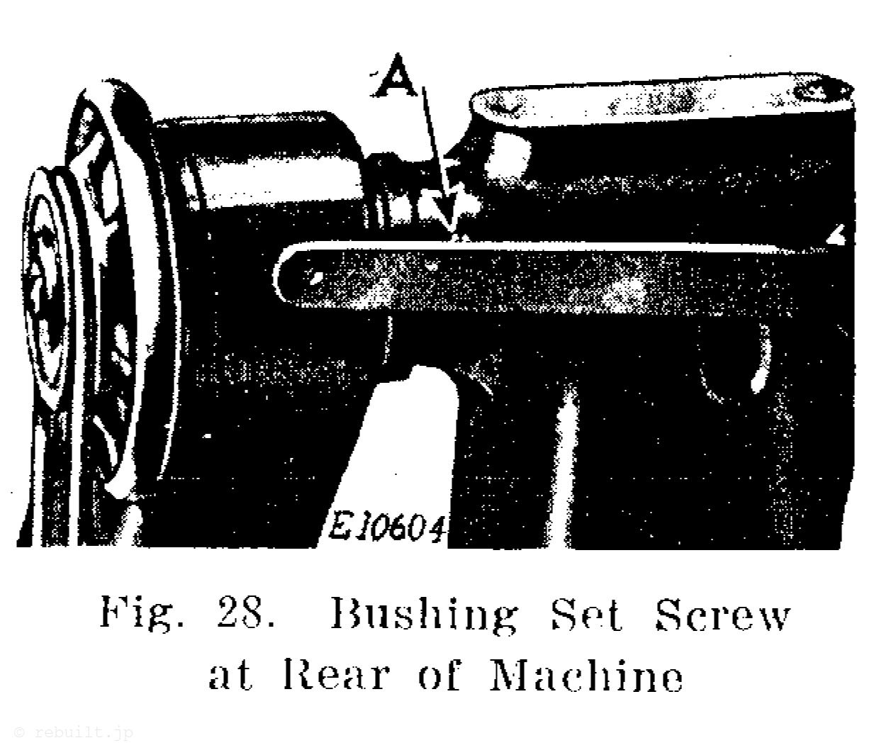
To Remove the Arm Shaft Remove the balance wheel, belt guard cover and belt, as instructed above. Remove the lower pulley (F. Fig. 27) from the bed shaft, then remove the upper pulley (G, Fig. 27) from the arm shaft, loosen the two set screws which hold the belt guard in position and remove the belt guard. Loosen the set screw (A. Fig. 28) at the rear of the machine, then remove the screw bushing (B. Fig. 2) and loosen both set screws in the ball bearing collar through the hole. Remove the posi- tion screw and loosen the set screw in the needle bar crank through the hole (1. Fig. 2). The arm shaft including the oil reservoir and rear ball bearing with the ball bearing housing can then be with- drawn from the machine.
Note: The set screw in the rear ball bearing collar on the arm shaft can be reached through the hole (C, Fig. 2).
To Remove the Bed Shaft Remove the balance wheel, belt guard cover and belt, as instructed on page 23. Remove the lower pulley (F, Fig. 27) from the bed shaft, then remove the upper pulley (G, Fig. 27) from the arm shaft, loosen the two set screws which hold the belt guard in position and remove the belt guard, also remove the bed cover plate. Loosen the two set screws (J, Fig. 20) in the ball bearing collar, loosen the two set screws in the gear (II, Fig. 20), loosen the two set screws in the feed lifting eccentric (E, Fig. 20), then loosen the bushing set screw (F, Fig. 2). The bed shaft including the gear (F. Fig. 20) and ball bearing with the ball bearing housing can then be withdrawn from the machine.
Note: The set screws in the rear ball bearing collar on the bed shaft can be reached through the hole (E, Fig. 2).
To Change the Gauge of the Machine. Remove the presser foot, throat plate, feed dog, hook cover plates and needle bar. Loosen the four screws (A, B, L and M, Fig. 20) in the hook saddles and spread apart the saddles. Place the new needle bar in the machine, set two new needles in the needle bar, then move the hook saddles toward the needles so that the points of the hooks will pass as close as possible to the needles without touching them, after which tighten the four screws (A, B, L and M). Set the needle bar at the correct height, as instructed on page 16. Fasten the new feed dog and throat plate in position in the machine. New hook cover plates must be used to correspond with the width of the new throat plate. It may be necessary to change the height or position of the feed dog, as instructed on page 21, also the position of the mechanical opener levers, as instructed on page 20.
℔ “The Singer Manufacturing Co. 出版のNo.288Wを当方が文字を起こした記事です。内容の記載に問題がある場合は問い合わせ先より連絡ください。