このページは、The Merrow Machine Company によって作られたミシンの説明書です。このミシンを使うにあたっての覚書として和訳したものです。
はじめに
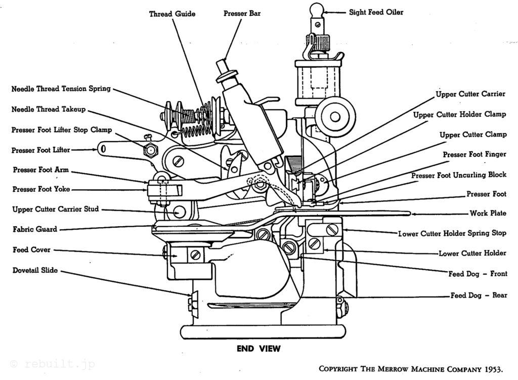
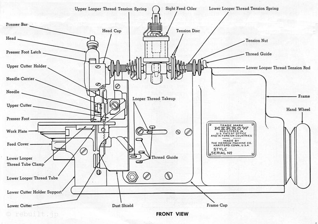
本書には、メロークラスAオーバーシーム、オーバーエッジング、ヘミングマシンの設定と操作方法、および各部品の位置を示す図が掲載されています。
クラスAマシンには、オーバーシームとトリミングを同時に行うマシンがあり、1本糸オーバーシーム、2本糸オーバーシームまたは仕上げ、3本糸オーバーシームまたは仕上げ、または3本糸タイトニードルスレッドシームを形成します。
また、クラス60オーバーシーム、オーバーエッジング、バットシーム、ヘミングマシン、プレーンクロッシェマシン、ブランケットヘミングマシン、シェルステッチクロッシェマシンなど、世界中のメーカーに長年にわたり好評を博している他のクラスのマシンも製造しています。メロークラスAオーバーシームで一般的に使用される多くの部品の詳細なリストを掲載した書籍をご希望の方は、お申し込みください。
ご注文方法
当社では、工場出荷時に各種ミシンに搭載されている各部品の型番を記録しており、部品名、ミシンのスタイル、シリアル番号をお知らせいただければ、複製品をご提供いたします。多数の部品の中から必要な部品がどれなのか判断できない場合は、部品名(2ページ目と3ページの図を参照)と、その部品をご希望のミシンのスタイルとシリアル番号をお知らせください。適切な部品を選定いたします。
ニードルプレートをご注文の際は、ご希望の仕上げ幅、長針・短針、使用する針のサイズをご指定ください。すべてのニードルプレートの部品番号は、プレートの裏面に刻印されています。ルーパーをご注文の際は、上糸か下糸か、2本糸か3本糸かをご指定ください。ミシンのスタイルとシリアル番号をお知らせください。部品番号は、すべてのルーパーの針尻近くのシャンクに刻印されています。
差動送り機構を備えた機械の送り機構部品を注文する際は、部品が前送り用か後送り用かを指定する必要があります。ほとんどの部品には文字または数字が刻印されています。重複して注文する場合は、部品名と刻印されている文字または数字をお知らせください。部品名を明記せずに、特定の部品に刻印されているだけでは十分な情報とは言えません。
マシンのセットアップ
1 マシンを箱から取り出したら、ネジ山をよく観察し、付属のネジ山図と比較してください。このネジ山図は、今後の参考のために保管してください。ネジ山の調整は非常に重要であり、作業に困難が生じた場合は、付属のネジ山図と照らし合わせてください。ネジ山の調整は簡単ですが、正確でなければなりません。
2 マシンをテーブルに固定します。付属のフェルトパッドの上にマシンを置き、付属のネジを使用します。マシンのハンドホイールはオペレーターの右側に配置し、マシンのベース前端はトランスミッターの中心線と平行になり、テーブルの前面から4~5インチ後方に配置されます。
3 注文時にVベルトハンドホイールが指定されていない限り、直径1/4インチ、太い、または直径5/16インチの丸革ベルトを使用したハンドホイールが付属します。トランスミッターからメローマシンまでのベルトが約30°の角度になるように、トランスミッターをテーブルの下に十分奥まで設置してください。
4 メローマシンのハンドホイールの上部は、操作者とは反対側を向いている必要があります。
5 糸立てを組み立て、そのベースをマシン背面のテーブルにねじ止めします。
6 糸立て上部の糸ガイドは、糸の円錐の中心の真上に来るようにする必要があります。
7 糸、毛糸、絹、またはレーヨンは、垂直に立てられた円錐に巻き付けます。これらの円錐からの糸は、糸立て上部まで伸び、そこから斜め下に向かってマシンに向かって伸びます。マシンの高速運転時に糸が絡み合わないよう、糸同士の間隔を十分に空けてください。
8 糸が円錐から容易に、均一な張力で抜けること、また円錐の下に引っかかったり、その他の理由で糸が抜けないことを確認してください。
9 各マシンにはオイルドレンが付属しています。セットアップするには、メローマシンフレームの下部にあるテーパープラグを取り外し、マシンに付属のオイルドレンパイプを挿入します。テーブルの上部に穴を開け、そこからオイル排出パイプを通します。オイル収集瓶と支柱は、オイル排出パイプの下、テーブルの下側に固定します。
速度
1 メロークラスAミシンは高速運転するように設計されており、多くのミシンが状況に応じて毎分4000~5000針で稼働しています。毎分5000針でも効率的に処理できる作業もありますが、多くの作業では毎分4500針の速度で最大効率が得られることが分かっています。
2 ミシンはそれほど手入れをしなくても問題なく稼働しますが、適切な注意を払うことでより良い結果が得られます。ミシンには丁寧に注油し、針キャリア、送り歯、ルーパー機構、そして排油チューブの周りの糸くずをきれいにしてください。排油チューブは、ミシン背面の開口部から清掃できます。
トランスミッター
機械の始動・停止の遅延を最小限に抑え、最大限の効率を得るには、トランスミッション装置を良好な動作状態に維持する必要があります。トランスミッション装置の配置にあたっては、大きなプーリーから比較的小さなプーリーへ、中心が近いプーリーへの駆動は避けてください。このような配置はベルトの滑りを過度に増加させ、メローマシンの始動・停止速度を著しく低下させるためです。
潤滑
1 メロークラスAマシンのベアリングは、高速性と耐久性を確保するために密着して取り付けられており、特に新品時は適切に給油する必要があります。100°F(華氏100度)でセイボルト粘度が約200の良質スピンドルオイルを使用してください。機械が十分に慣らし運転された後は、やや粘度の高いオイルを使用できます。お客様からは、良質なSAE 20粘度の自動車用オイルを使用することで良好な結果が得られたとの報告があります。いわゆる「ステンレス」オイルは、この用途には推奨しません。
2 ミシンのフレームキャップのすぐ上にあるサイトフィードオイラーは、このアセンブリの高速で動く内部部品にオイルを供給し、ミシンの他の部品には供給しません。このオイラーのニードルバルブは、オイルが満タンの状態で3~4時間持続するように設定する必要があります。ミシンに備えられている他のすべてのオイル穴にも、状況に応じて3時間ごとにオイルを注入する必要があります。これらのオイル穴は、上下のシャフトの両端、ニードルキャリア、押さえ足、送り機構、送り偏心装置にオイルを供給します。
針
1 針をニードルキャリアにセットし、針のシャンクの先端がニードルキャリア後部のストップピンに接触するようにします。付属のソケットレンチでニードルクランプナットをしっかりと締め付けますが、締め過ぎにはご注意ください。ニードルクランプナットの斜面部分は、ニードルクランプカラーに設けられたニードルクランプナット用の凹部に接する必要があります。
2 作業内容に応じて可能な限り大きな針を使用してください。ただし、ニードルプレートのニードルスロットが針に十分な大きさであることを確認してください。
3 クラスAミシンの全機種で使用される、サイズ番号と文字「D」が刻印されたセルフセッティング針は、以下のサイズで製造されています。GOOD、GOD、GD、ID、2D、3D、4D、5D、8Dで、GGGDが最も細いサイズです。上記のサイズの一部には、特殊用途向けの特殊針も用意されています。
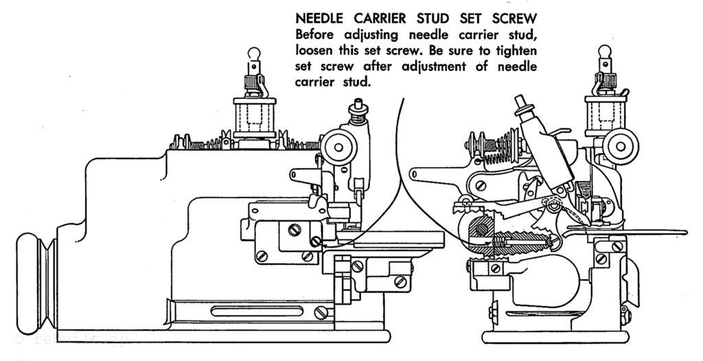
ニードルキャリア
ニードルキャリアは、スタッド上で完全に自由にスイングできる必要がありますが、横方向の動きがあってはなりません。この調整は、まずニードルキャリアスタッドの止めネジを緩めることによって行います。この止めネジは、ミシンのフレーム内、ニードルキャリアスタッドの中心のすぐ後ろに位置し、ミシン背面の外側からアクセスできます。(4ページ参照) このネジを一度でも緩め忘れると、ミシンのフレームのネジ穴が損傷する可能性があります。止めネジを緩めた後に調整するには、ニードルキャリアスタッドをわずかに内側または外側に回して適切な調整が得られたら、ニードルキャリアスタッドの止めネジを締めます。
ニードルプレート
1, 3本糸仕上げや縫い目には通常、希望するステッチ幅のチェインフィンガーを備え、かつ、生地がミシンに送られる際に2~3針がフィンガーに保持されるのに十分な長さのニードルプレートが必要です。
2. 2本糸端仕上げや縫い目には通常、非常に短い、または「スタブ」フィンガーを備えたニードルプレートが必要です。このような針板を使用する場合、チェーニングフィンガーは押え金と押え金フィンガーの一部に固定されます。
3 . 針板の針溝は、針の刃が針板に接触することなく自由に通過できる大きさでなければなりません。この溝の縁は直角でありながら滑らかで、わずかに丸みを帯びている必要があります。チェーニングフィンガーまたは針板の作業面に、凹凸やざらざらした部分がないことを確認してください。
4. 薄い「柔らかい」生地に使用する針板の作業面は、差動送り動作をほとんど必要としないため、波型であってはなりません。
下ルーパー
1. 下ルーパーはほぼ自動的にセットされるようになっていますが、針と正しく連動させるには若干の曲げが必要になる場合があります。下ルーパーは、上ルーパーをミシンにセットする前、および前述のように針を正しくセットした後にセット・調整するのが最適です。ルーパーをセットする準備として、押さえ金を所定の位置から回し、針板、糸通し管、送り歯、防塵カバーを取り外してアクセスできるようにします。下ルーパーをセットするには、下ルーパーキャリアの止めネジを緩め、ミシンのハンドホイールを回して、下ルーパーキャリアの上部が最も右側の位置に近づきます。次に、下ルーパーの先端をキャリアに挿入し、できるだけ奥まで押し込みます。次に、止めネジを下ルーパーの平面に締め付けます。ミシンのハンドホイールを手でゆっくり回し、下ルーパーと針の関係を確認します。針は下降時に、直角曲げ部付近の下ルーパーのシャンクに軽く、しかし過度に接触しないようにする必要があります。この確認と調整を行った後、針が上昇を開始し、下ルーパーの先端が針を通過するまで、ミシンを手で回し続けます。
下ルーパーの先端は針に軽く、しかししっかりと接触する必要がありますが、針を曲げてはなりません。必要に応じて、ルーパーをわずかに曲げて調整してください。
2 . ルーパーを曲げる必要がある場合は、必ず希望する方向に少し曲げてから、ルーパーを元の位置に戻してください。そうしないと、使用中にルーパーが徐々に元の位置に戻ってしまいます。
3. ルーパーを曲げたり曲げたりする場合は、必ず表面が滑らかなペンチを使用してください。下ルーパーの調整が細かい場合は、ルーパーをミシンから取り外し、滑らかなジョーのバイスで固定し、滑らかなジョーのペンチで曲げてください。
4. 調整後は、必ず下ルーパーの止めネジが適切に締められていることを確認してください。
上ルーパー
上ルーパーはほぼ自動的にセットされますが、下ルーパーおよび針板上の針と適切に連動させるために、曲げる必要がある場合があります。これらのルーパーには、2本糸縫い用と3本糸縫い用の2つの一般的な形状があります。2種類のルーパーの一般的な調整方法は同様です。下ルーパーをセットした後、上ルーパーを上ルーパーキャリアに挿入し、フレームキャップの前面中央部分の開口部の左端からアクセスできる止めネジで固定します。上ルーパーをキャリアに完全に押し込んだ後、この止めネジを上ルーパーに設けられた平面に締め付けます。ミシンを手でゆっくりと回転させます。上ルーパーの先端は、下ルーパーの針穴のすぐ後ろにある下ルーパーの凹部を通過する必要がありますが、先端が下ルーパーのこの凹部の底に実際に接触してはいけません。上ルーパーの前面は、上記の凹部の右側にある下ルーパーの針穴の周りの膨らみを通過する必要があります。この調整を行った後、ミシンをゆっくりと回し、上ルーパーと針の調整状態を確認します。上ルーパーは針に当たらないようにし、針先がルーパーの裏側、つまりルーパーの穴または針穴のすぐ右側に設けられたくぼみを通過するようにします。この調整を行うには、必要に応じてルーパーを上下に動かします。ルーパーを曲げる必要がある場合は、前のセクションの下ルーパーの説明に従って操作してください。
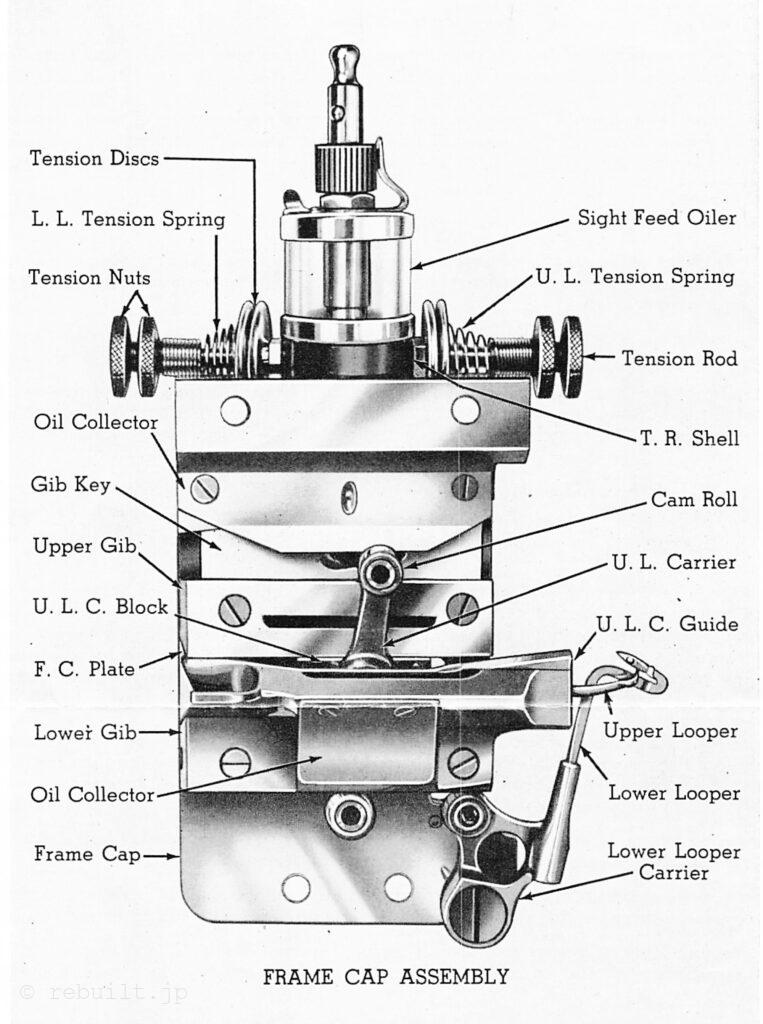
フレームキャップ
フレームキャップを取り外すには、ダストシールドと上下のルーパーを取り外し、ミシンを回転させて下ルーパーキャリアを右端の位置まで移動させ、フレームキャップを固定している4本のネジ(上2本、下2本)を外します。フレームキャップは作業者側に引いてミシンから簡単に取り外すことができます。組み立て直すには、カムロールを上下のキャリアに所定の位置に取り付け、オイルを塗布します。ハンドホイールを回し、下カムの左側の溝を確認します。溝の右端が作業者側を向いた状態で下カムを止めます。フレームキャップは取り外した位置まで持ち上げることができます。
下ルーパーキャリア
下ルーパーキャリアは、フレームキャップの左下隅にねじ込まれたテーパースタッドで支持されており、フレームキャップの外側にあるナットで固定されています。キャリアはテーパースタッド上で完全に自由にスイングでき、かつ横方向の動きがほとんどないことが求められます。調整は、まずテーパースタッドを固定しているナットを緩めて、スタッドが回転できる程度に締めます。スタッドを必要な方向に少しだけ回し、固定ナットを締め直します。下側のルーパーキャリアは、締めすぎるよりも少し緩めておく方が望ましいです。
上フーパーキャリア、上フーパーキャリアブロックおよび
上フーパーキャリアガイド
1 . 上ルーパーキャリアは上ルーパーキャリアブロックに枢動固定されており、アセンブリはどちらの方向にも完全に自由にストローク移動でき、かつロストモーションがほとんどないことが求められます。上ルーパーキャリアブロックは上下端が面取りされており、フレームキャップの内側に固定された上部ギブと下部ギブの間をガイドされながら移動します。下部ギブは固定されており、上部ギブは、ジブキーのスロット穴にねじ込まれたネジでフレームキャップに固定された上部ギブキーによって調整可能です。この調整を行う際は、ストロークのどの部分でも上ルーパーキャリアブロックを挟んだり、拘束したりしないように注意してください。この調整は、締めすぎず、やや緩めに行うのが望ましいです。両端がミシン内部のフレームキャップアセンブリにしっかりと固定された上ルーパーキャリアガイドは、上ルーパーキャリアの前後ストロークを拘束し、横方向の動きを制限する役割を果たします。
2. この上部ルーパーキャリアガイドの支持点の下には、長方形のシムと円形のシムが設けられています。これらのシムには両方とも、厚さを1000分の1インチ単位で示す数字が刻印されています。必要に応じて、1000分の1インチ厚または1000分の1インチ薄いシムをどちらのタイプでも取り付けることができます。ルーパーキャリアガイドを調整する際には、ガイドがしっかりと固定されたときに、ガイドと上部ルーパーキャリアの間に約1000分の2インチの均一な隙間ができるように、両端に適切なシムを設ける必要があります。
3. 上記の上部ルーパーキャリアブロックと上部ルーパーキャリアガイドの調整は工場で行われ、事故やオイル不足による部品の損傷がない限り、ほとんどの機械は4~5年間再調整なしで稼働します。
4. 上部ルーパーキャリアの両端のスタッドには、カム溝内を移動するカムロールが取り付けられています。上部ルーパーに過度の垂直方向の緩みがある場合、これらのカム ロールを交換する必要がある可能性があります。これは、フレーム キャップを取り外すだけで簡単に実行できます。
押さえ金と押さえフィンガー
ほとんどのミシンには、中央ヒンジの押さえ金が標準装備されています。これは、縫い目や厚手と薄手が交差する箇所の縫い合わせや縁取りに便利です。これらの押さえ金はシャンクに固定されており、押さえ金ラッチを上げるとシャンクが片側にスライドし、針やルーパーへのアクセスが容易になります。特殊な用途向けに、固定式と後部ヒンジ式の押さえ金も用意されています。押さえには、針の右端を保護する「調節可能な押さえフィンガー」が付いており、針に隣接する押さえフィンガーの左端が針板のスロットの右端をちょうど覆うように調整する必要があります。ミシンにチェーンフィンガー付きの針板が装備されている場合は、「スタブ」または短い押さえフィンガーが使用されます。ミシンにスタブまたは短いチェーンフィンガー付きの針板が装備されている場合は、長い押さえフィンガーが使用されます。通常、押さえには可能な限り小さな圧力をかけます。圧力の程度は、ミシンのヘッド上部にある押さえバネ調整ネジで調整できます。このネジは、ヘッド上部の右側にある小さなセットネジで調整されます。
上カッターと下カッター
1 . 下カッターは下カッタークランプによって下カッターホルダーに固定されています。クランプナットは下カッターホルダーの左側からアクセスできます。カッターの刃先は針板上面よりわずかに上になるように設定する必要がありますが、押さえ足の下面に接触するほど高く設定しないでください。上カッターは上カッタークランプとネジによって上カッターホルダーに固定されており、その中で斜めに調整可能です。上カッターが最も低い位置にあるとき、刃先が下カッターの上端よりわずかに下になるように設定してください。両方のカッターがしっかりと固定されていることを確認し、ミシンを手で裏返してください。上カッター後部の突起部は常に下カッターに接触している必要があります。
2 . カッターをセットするときは、生地が、糸が形成されるチェーニング フィンガーの部分の幅とほぼ同じ幅にトリミングされるように、右または左に設定する必要があります。ほとんどのクラス A マシンには、上部カッターと下部カッターの間に均一な圧力を維持するためのスプリングが付いた下部カッター ホルダーが備えられています。この下部カッター ホルダーにはクランプ装置も備えられており、下部カッター ホルダー サポートの前部にある簡単にアクセスできるネジで締めます。特定の重い作業では、この下部カッター ホルダーのクランプ ネジを締めることが望ましい場合があります。下部カッターを上部カッターに強く押し付けすぎないように注意してください。スプリングによって通常得られる圧力よりも強い圧力が必要な場合は、通常、カッターが鈍くなっていることを示すため、研ぐ必要があります。
送り歯
1. 送り歯には、作業内容に応じて、細目歯または粗目歯、単列または複列歯のいずれかが備えられています。一般的に、送り歯は可能な限り低く設定する必要があります。送り長さは、下軸の左端に固定されている送り偏心輪を取り外し、異なる送り量の送り偏心輪に交換することで変更できます。送り偏心輪には、布端で1インチあたりに生産されるステッチ数の目安となる目盛りが付いています。
2 . 送り歯と針板は互いに一致している必要があり、1インチあたりのステッチ数が非常に少ない場合は、針板との干渉を防ぐために送り歯を交換する必要がある場合があります。
3 . 様式表示に「D」の文字で示されるミシンには、差動送りまたはギャザー送りが搭載されています。差動送りには、それぞれ独立した送りキャリアと送り偏心輪を備えた2つの独立した送り歯が含まれています。縫い合わせや端仕上げの際に布端が伸びたり長くなったりするのを防ぎたい場合は、前方送り歯を後方送り歯よりも大きく動かすために、後方送り歯よりも送り偏心輪を大きく動かします。ほとんどの場合、わずかな差で十分であり、各送り偏心輪の数と2つの送り偏心輪の差は、1インチあたりに必要なステッチ数と布地自体の伸縮性によって決まります。一部のミシンには、送り歯の横方向の動きを防ぐための送り安定装置が装備されています。安定ネジは、送りキャリアがあらゆる位置で完全に自由になるように調整する必要があります。
糸通しワイヤー
1 . ルーパー糸に糸を通す際は、ミシンに付属の糸通しワイヤーを使用すると便利です。ワイヤーの一端には、糸を受けるためのループが設けられています。糸通しワイヤーの反対側の端を糸通し穴またはチューブに通し、糸をワイヤーとともに引っ張ります。
2 . 3本糸ミシンの上ルーパー糸に糸を通す際は、糸通しワイヤーを比較的大きな円弧状に曲げてからダストシールドのチューブに通すのが望ましいです。チューブに通した後、ワイヤーの先端が針板の上、上ルーパーの前方に出てくるため、ワイヤーを掴んで糸をワイヤーとともに引っ張ることができます。
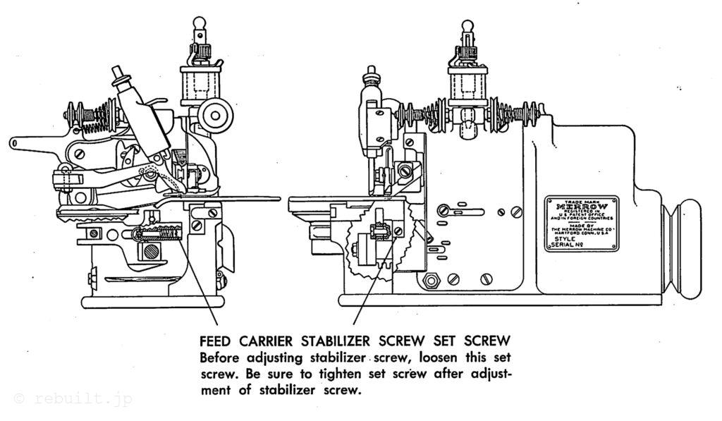
フィードキャリアスタビライザースクリューセットスクリュー
スタビライザースクリューを調整する前に、このセットスクリューを緩めてください。スタビライザースクリューの調整後は、必ずセットスクリューを締めてください。