To Set the Needle
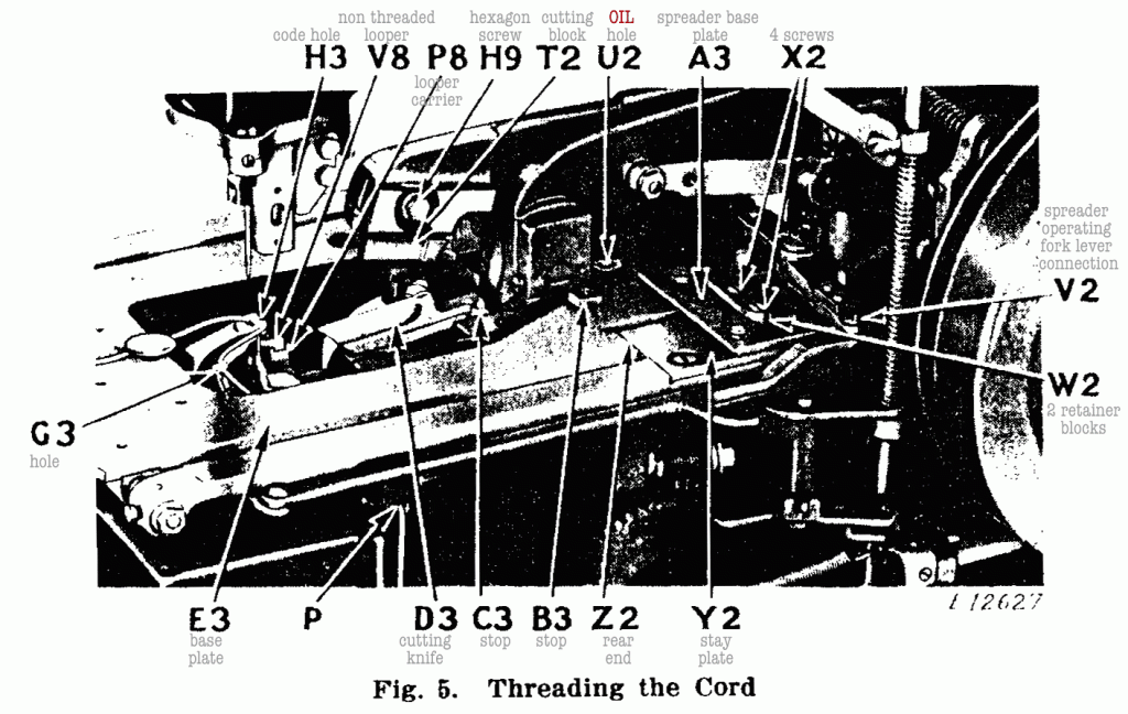
¶ Loosen the set screw (Q7, Fig. 13) in the needle clamp and put the needle up into the clamp as far as it will go with its long groove to the rear and its eye parallel or in line with the bed of the machine, then firmly tighten the set screw (Q7,Fig 13).
To Thread the Needle
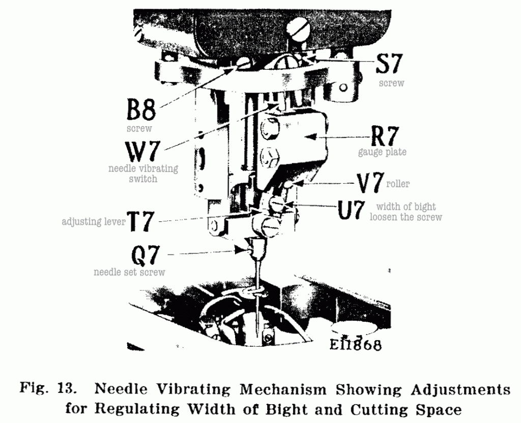
¶ Pass the thread from the unwinder down through the hole (1, Fig. 2)❶ in the upper end of the needle thread leader, through the hole (2, Fig. 2)❷ in the lower end of the needle thread leader, from back to front under between the tension discs (3, Fig. 2)❸,
up through the slotted hole in the take-up thread guide (4, Fig. 2)❹, down through the forward hole (5, Fig. 2)❺, down through the hole in the end of the thread take-up (6, Fig. 2)❻, through the hole (7, Fig. 2)❼ in the top of the needle thread guide pin, under the needle thread pull-off (adjustable) (9, Fig. 2)❽ and down through the hollow needle bar (8, Fig. 2)❾ (inserting the thread- ing wire furnished with the machine up into the needle bar from below to pull the thread through), pass the thread from back to front or toward you through the eye of the needle, as shown in Fig. 6.
Note: ¶ When it is necessary to place the thread unwinder at the side of the machine, the needle thread leader (1, Fig. 2) at the top of the machine should be turned in the direction of the unwinder and the thread should be passed through the hole (A, Fig. 2) instead of the hole (2, Fig. 2).
To Thread the Looper
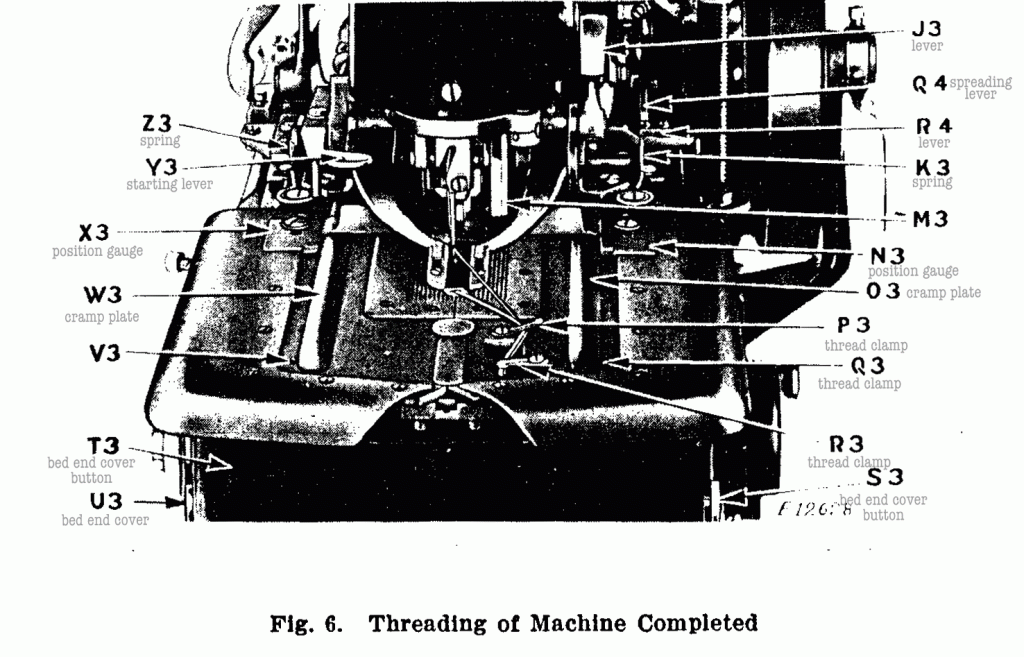
¶ Unhook the two springs (K3 and Z3, Fig. 6) and swing out the two work clamp plates (O3 and W3, Fig. 6), then press in the buttons (S3 and U3, Fig. 6) and at the same time draw the bed end cover (T3, Fig. 6) toward you to remove it from the machine.
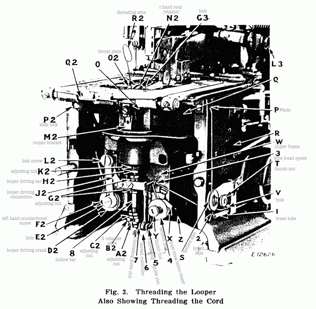
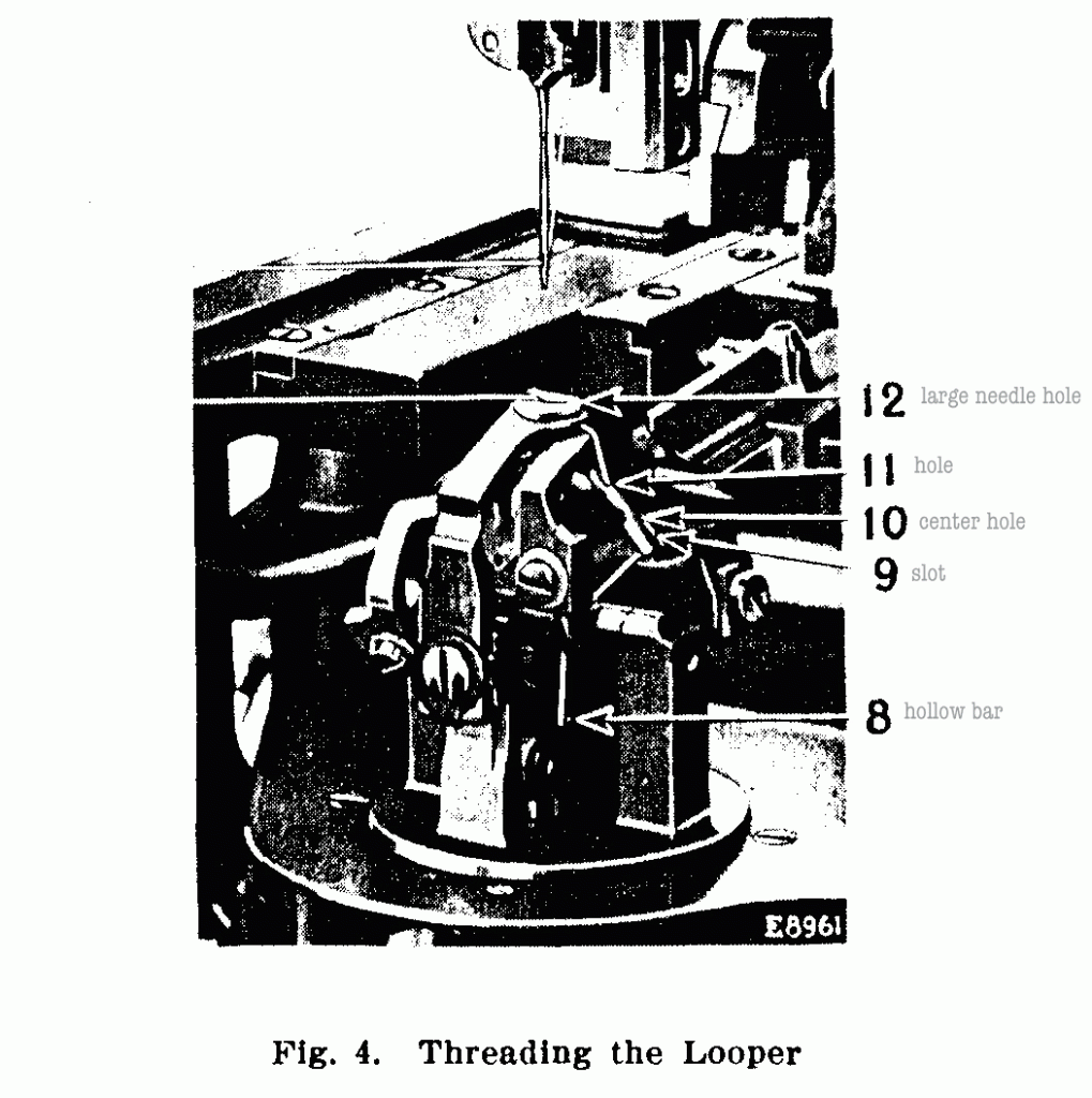
¶ Pass the thread from the unwinder through the lower brass tube (1, Figs. 3 and 10)❶ which is attached to the right side of the bed of the machine (using the threading wire furnished for the purpose), then through the lower hole (2, Fig. 3)❷ in the bed of the machine at the front of the brass tube, through the wire thread eyelet (3, Fig. 3)❸, down, under and from right to left between the tension discs (4, Fig. 3)❹, from right to left through the right hand self-threading guide slot (5, Fig. 3)❺ in the thread controller bracket, through the slot in the thread controller (6, Fig. 3)❻ and through the left hand self-threading guide slot (7, Fig. 3)❼ in the thread controller bracket. Pass the threading wire (R2, Fig. 3) between the throat plate (O2, Fig. 3)❽ and right hand loop retainer (N2, Fig. 3)❾ down through the hollow loop retainer driving bar (8, Figs. 3 and 4). Hook the thread on the end of the wire and draw it up through the hollow bar (8, Figs. 3 and 4), then, using the tweezers furnished for the purpose, pass the thread from the hollow bar (8)① up through the slot (9, Fig. 4) ②in the heel of the looper, as illustrated in Fig. 4, down through the centre hole (10, Fig. 4) ③ in the looper and up through the hole (11, Fig. 4)④ in the point of the looper, then up through the large needle hole (12, Fig. 4)⑤ in the throat plate.
To Thread the Cord
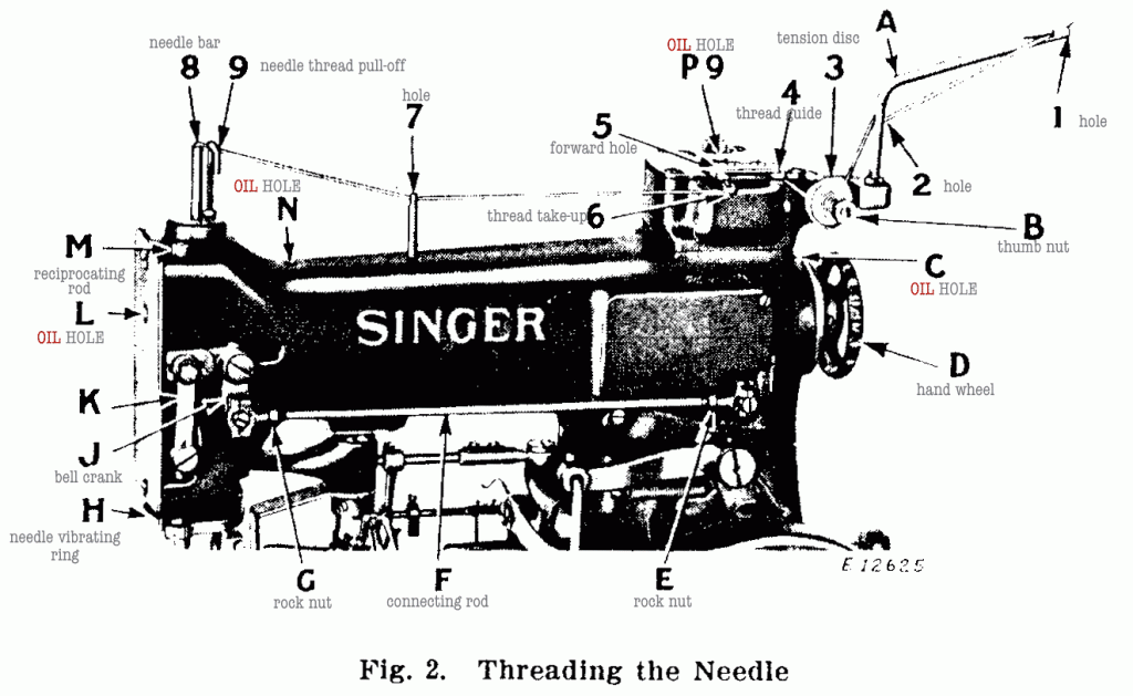
¶ The work clamp plates having been swung outward and the bed end cover removed, pass the cord from the unwinder through the upper brass tube (V, Figs. 3 and 10)❶ which is attached to the right side of the bed of the machine (using the threading wire furnished for the purpose), then pass the cord under and between the tension discs (S, Fig. 3)❷ adjacent to the cord tube, through the hole (P, Figs. 3 and 5) ❸ in the right hand side of the bed of the machine, up through the hole (G3, Fig. 5) ❹ in the cord controlling spring, thence from back to front through the cord hole (H3, Fig. 5) ❺ near the center of the throat plate, the cord leading toward the operator as shown in Fig. 5. ¶ Then swing the work clamp plates back into place and hook the springs (K3 and Z3, Fig. 6) ❻ to hold the plates in position. ¶ Also replace the bed end cover, then clamp the ends of the cord and looper thread in the thread clamps (P3 and R3, Fig. 6)❼.
