¶ Diagram, Fig. 7, shows order of operation of mechanism in Machines 99w130 to 99w132 during the cutting and stitching of a buttonhole from start to finish.
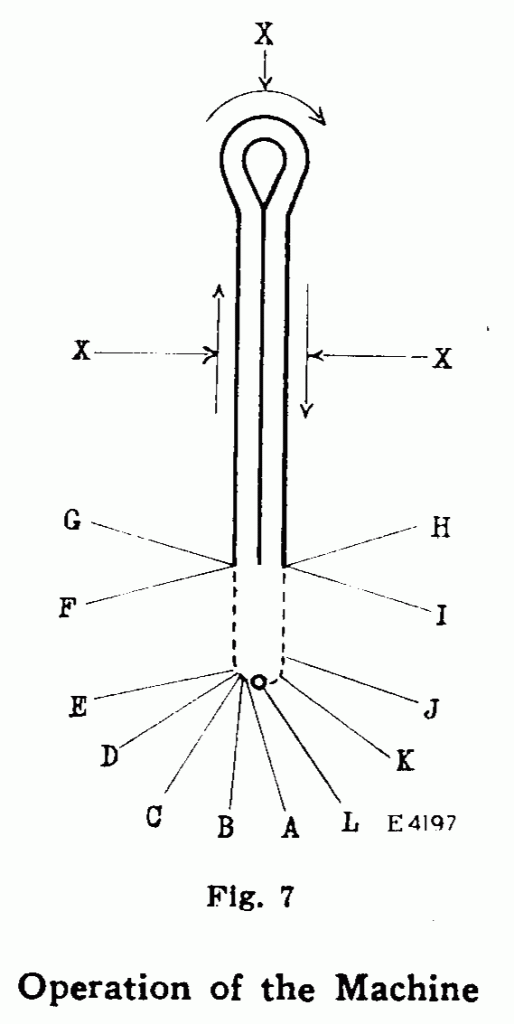
A -Work Clamps are closed by Clamp Closing Lever
B -Buttonhole Cutter is tripped by Clamp Closing Lever
C -Buttonhole is cut by Buttonhole Cutting Shaft
D -Buttonhole is spread by Buttonhole Cutting Shaft
E -Rapid Feed is started by Buttonhole Cutting Shaft
F -Sewing is started by Pattern Wheel Ring
G -Rapid Feed is stopped by Pattern Wheel
X -Buttonhole is stitched (indicated by solid line)
H -Sewing is stopped by Pattern Wheel Ring
I -Rapid Feed is started by Stop Motion
J -Work Clamps are opened and Spread is released by Trip Point on Work Plates
K -Rapid Feed is stopped by Pattern Wheel
L -Starting and stopping point Dotted line represents rapid feed
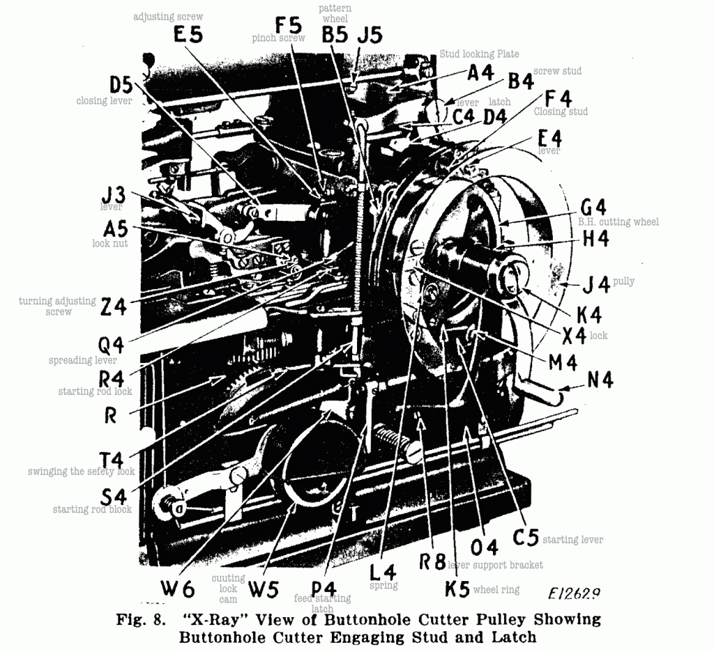
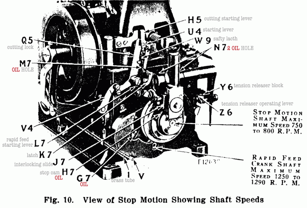
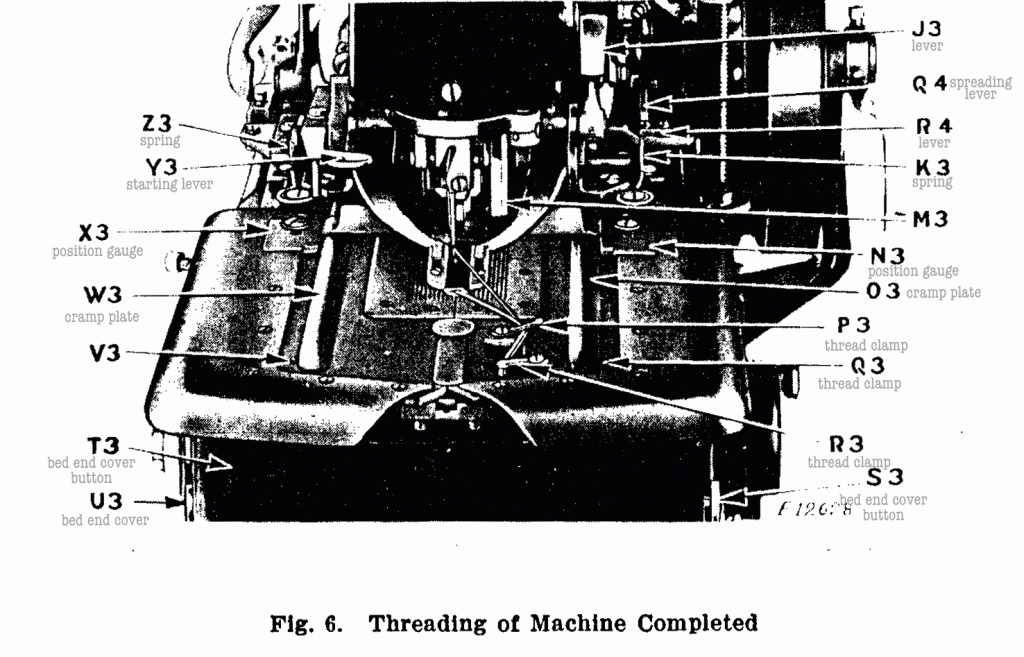
¶ The operator should sit a little to the left of the center of the front of the machine so that the opening in the work clamps can be fully seen. This position will be found to be the most con- venient for the operator for the reason that the work is moved from left to right in the machine when passing from one button- hole to another, and also because the finger starting lever is located above the left work clamp plate. ¶ Unlock the machine by pushing the safety lock (T4, Fig. 8) inwardly. Place the work in position in the machine so that the portion in which it is desired to make the buttonhole is directly under the opening in the work clamps. ¶ Then set the two work position gauges (N3 and X3, Fig. 6) against the edge of the work and fasten them in position. ¶ Hold the work firmly in position with the hands and at the same time press down on the finger starting lever (Y3, Fig. 6). This will trip the lever (C4, Fig. 8) out of the locking notch in clamp closing stud (F4, Fig. 8). ¶ The plunger will then be held out of engagement with the cam path in the pulley (J4, Fig. 8) by latch (D4, Fig. 8) holding the locking notch in the stud (F4, Fig. 8) until the cam path is in the correct position to receive the stud, at which time the tripping cam block on the inside face of pulley (J4) will trip the lever (E4, Fig. 8), lifting the latch (D4) and allowing the stud (F4) to engage the cam path in pulley (J4), causing the clamp closing lever (D5, Fig. 8) to be depressed and the work clamps to be lowered upon the work. ¶ The stud (F4, Fig. 8) is forced inwardly, by the stud disengaging cam block mounted in the cam path of the pulley (J4, Fig. 8), under the stud lock plate (A4, Fig. 8) into locking position and held by the lever (C4, Fig. 8) in the locking notch. ¶ As the clamp closing lever returns to its starting position, the starting lever trip (U4, Fig. 10) is forced against the starting lever arm (H5, Fig. 10), which in turn actuates the buttonhole cutting starting lever (B5, Fig. 8), causing the latch (X4, Fig. 8) in the buttonhole cutting wheel to engage the loose buttonhole cutting pulley. ¶ As the buttonhole cutting wheel (G4, Fig. 8) is fastened in a rigid position on the buttonhole cutting shaft (K4,Fig. 8), the shaft is rotated when the wheel and loose pulley are locked together by the latch (X4, Fig. 8). When the button- hole cutting shaft starts to rotate, the buttonhole cutting levers are moved into action by the operating cams on the buttonhole cutting shaft, and the cutting block and knife are carried forward to cut the buttonhole. ¶ After the buttonhole cutter has cut the buttonhole, the safety latch (W9, Fig. 10) is moved beneath the starting lever trip (U4, Fig. 10) and holds it out of engagement with the starting lever arm (H5, Fig. 10). ¶ As the cutting levers return to their starting position, the spreading lever (Q4, Figs. 6 and 8) is pushed forward against the lever (R4, Figs. 6 and 8), thus spreading the work clamps and stretching the fabric taut under the needle. ¶ During the last part of the rotation of the cut- ting shaft, the rapid feed starting lever (C5, Fig. 8) is operated, causing the rapid feed to move the work clamp plates with the work to a stitching position, after which the latch (X4, Fig. 8) in the buttonhole cutting wheel is withdrawn from the loose but- tonhole cutting pulley, releasing the wheel from the pulley and stopping the rotation of the buttonhole cutting shaft. (¶ At the same time, the cutting lock cam (W5, Fig. 8) actuates the rock shaft lever (V4, Fig. 10), forcing the cutting lock (Q5, Fig. 10) beneath the starting lever trip (U4, Fig. 10), thus locking the cutting mechanism so that it cannot operate while the buttonhole is being stitched.)
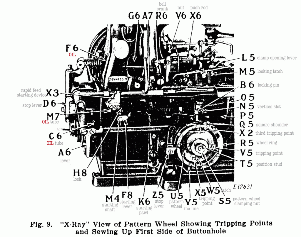
¶ When the work clamp plates are brought to the stitching position, the rapid feed is disengaged by the tripping point (V5, Fig. 9) on the inner side of the pattern wheel (U5, Fig. 9) com- ing into contact with the latch (W5, Fig. 9), and the stitching mechanism is started in operation by the action of the stop lever operating plate (Z5, Fig. 9) riding up the incline (Y5, Fig. 9) on the pattern wheel ring, causing the stop lever (D6, Fig. 9) to swing back out of engagement with the stop cam on the sewing pulley. ¶ The machine then stitches the buttonhole and at the completion of the stitching, the stop lever operating plate (Z5, Fig. 9) drops off at the square shoulder (Q5, Fig. 9) on the pattern wheel ring, causing the stop lever to swing in, ready to lock in the stop cam on the sewing pulley. ¶ As the interlocking slide (J7, Fig. 10) is raised by the action of the stop cam (H7, Fig. 10), the point of the latch (K7, Fig. 10) is lowered fully f inch below the end of the second rapid feed starting lever (L7, Fig. 10). As the interlocking slide (J7, Fig. 10) drops into the notch of the stop cam (H7, Fig. 10), it raises the latch (K7, Fig. 10) which in turn raises the second rapid feed starting lever (L7, Fig. 10) as it comes into contact with it, thereby starting the rapid feeding mechanism in operation to move the clamp plates back to a starting position for the next buttonhole.
